
|
It is currently Fri Apr 19, 2024 2:28 am |
|
All times are UTC - 8 hours |
 |
|
|
Page 24 of 31 |
[ 454 posts ] | Go to page Previous 1 ... 21, 22, 23, 24, 25, 26, 27 ... 31 Next |
| Print view | Previous topic | Next topic |
1926 Model TT Restoration: Engine/Trans Rebuild
| Author | Message |
|---|---|
|
Site Supporter   Location: Tacoma Joined: Sat May 4, 2013 Posts: 6214 |
Time to tackle the bottom end. Here is what it looks like. Thats the camshaft on the left. Underneath the camshaft are the lifters which actuate the valves.
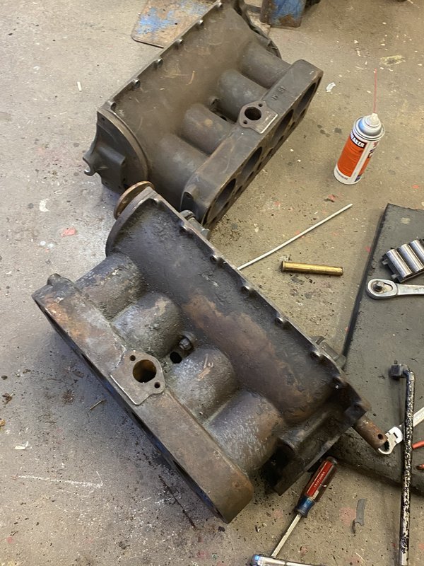
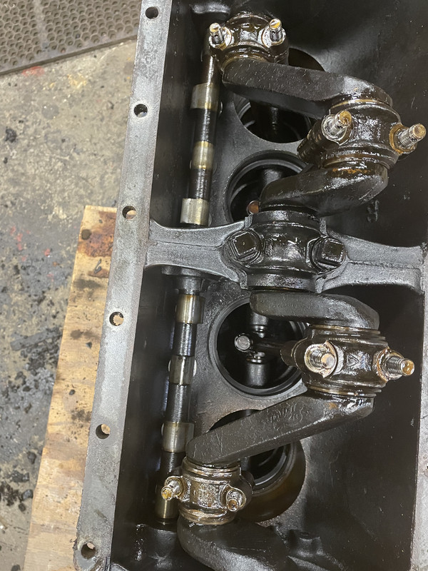 Unbolt the caps from the connecting rods 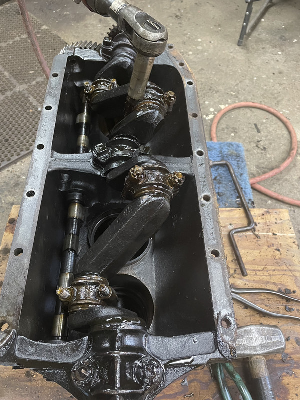 Ready to remove the pistons. These pistons are not factory. They are 0.030 inch over, and were installed by my dad about 30 years ago. Fast forward to today, and cylinder wall wear would indicate that I would need 0.060 or 0080 over pistons. However, my block is cracked, so no matter. 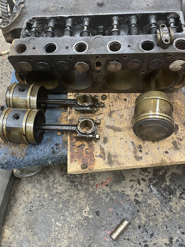 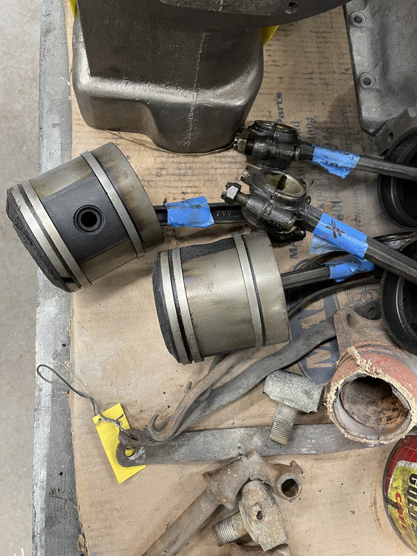 This is the front of the engine. 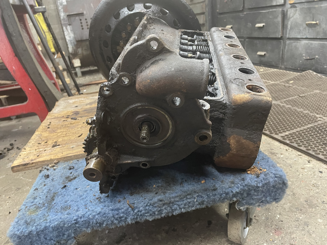 Reverse side of the front cover 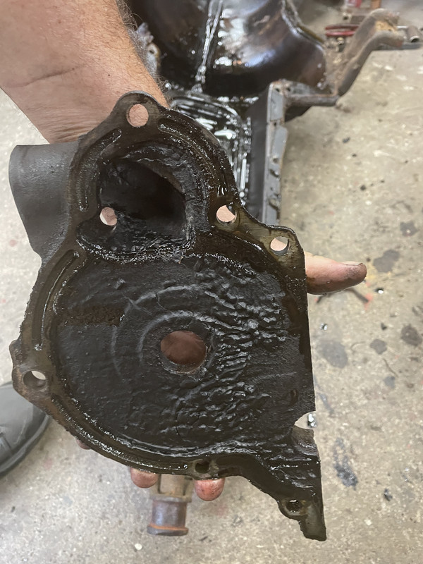 Under the front cover is the crank gear and timing gear. Timing gear is the big one. It is mounted on the front end of the camshaft 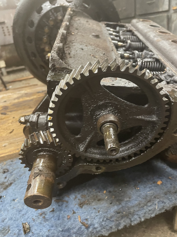 On the back end of the engine, where it meets the transmission, there is a oil tube that carries oil from the transmission to the front main bearing. If this tube gets plugged, you will melt the front main bearing. For this reason, many people plumb a second, external, copper line from the transmission to the front bearing. I had one on my old engine, and will put one on my new engine. Cheap insurance. The oil tube comes out and the magneto coil assembly is unbolted and removed 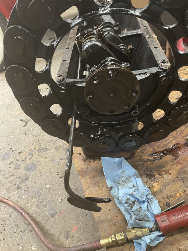 Time for the crank to come out. The bolt holding the main bearing caps on are 4-sided. There is a special Model T wrench for these bolts. 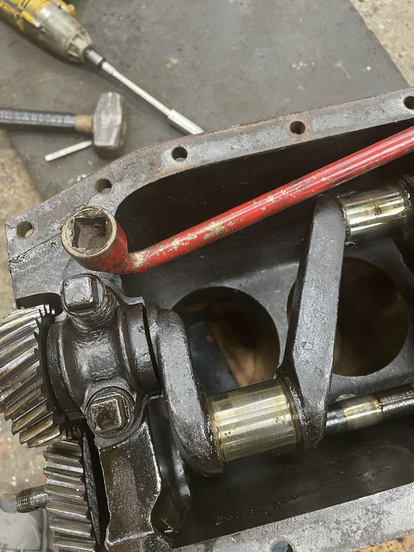 Here is a main bearing cap and shims. The brass shims are multi-layer. As the bearing wears out, you pull the cap, peel off a layer of shim and put the cap back on. That tightens up the bearing. 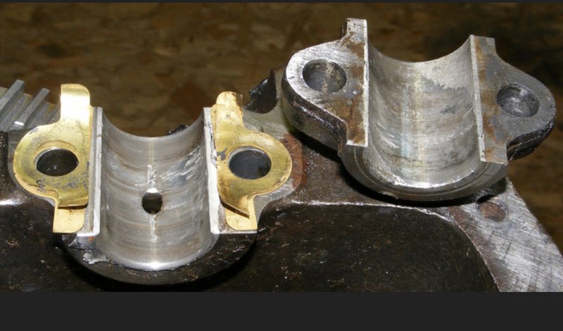 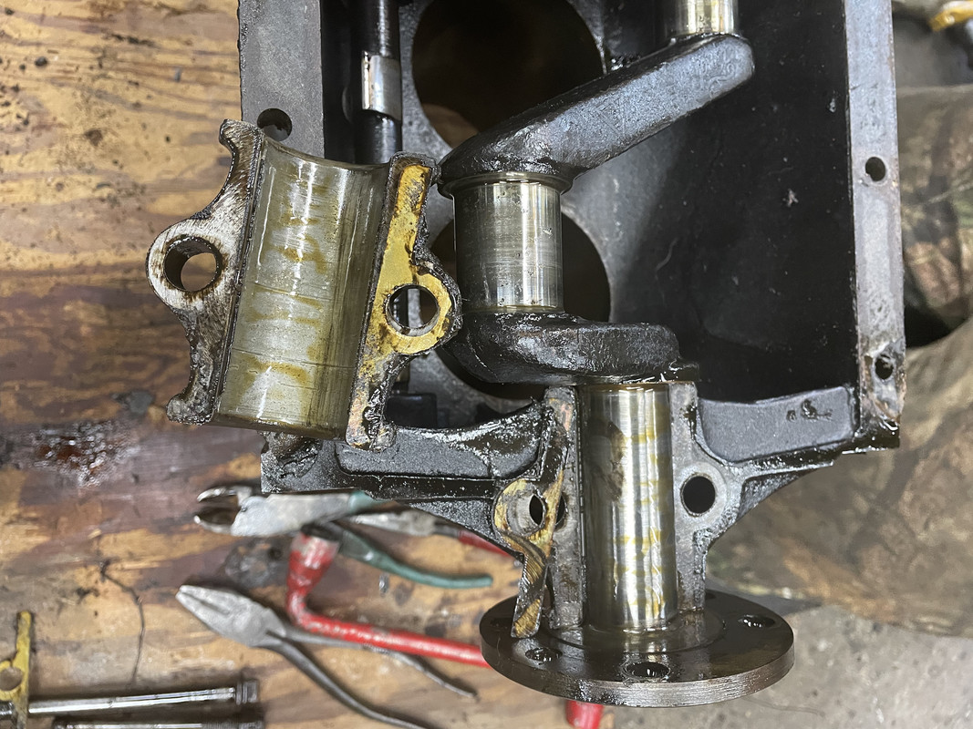 Here is the crank removed 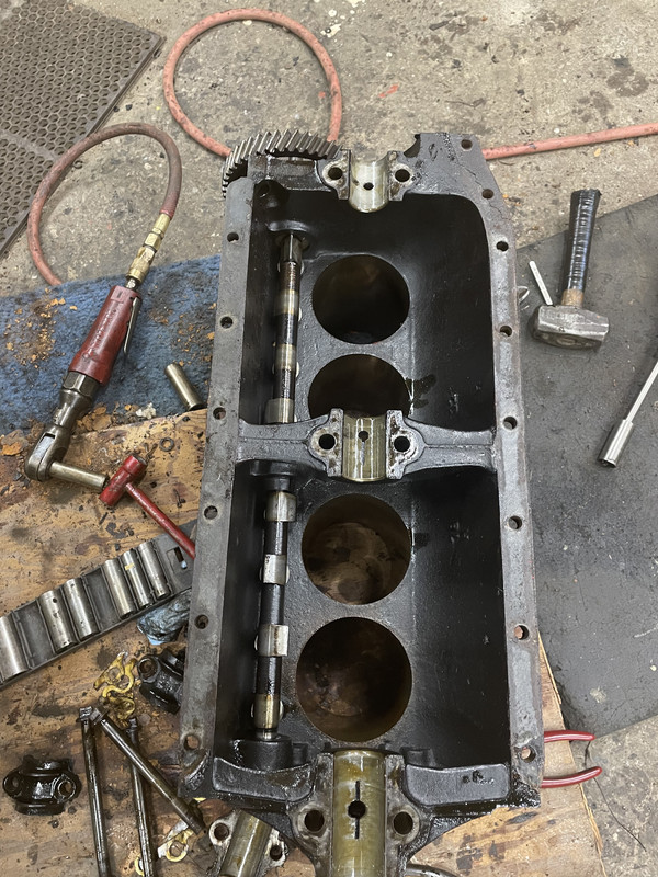 Hare a couple of Model T cranks  Time to pull the camshaft. 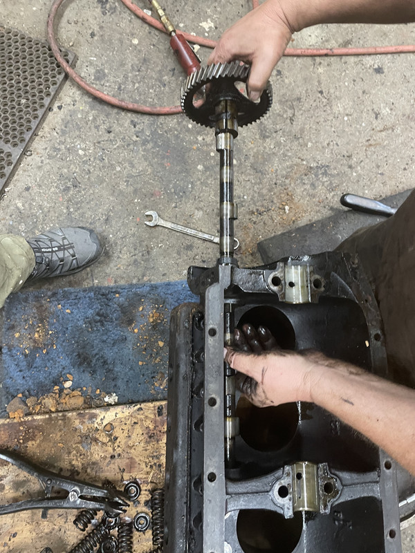 With the cam out, you can see the lifters. My thumb is resting on the center camshaft bearing. There is also a front bearing and a rear bushing the cam rotates in. 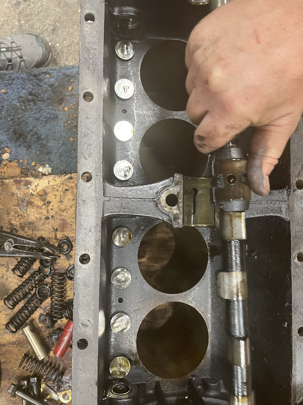 Here is a lifter 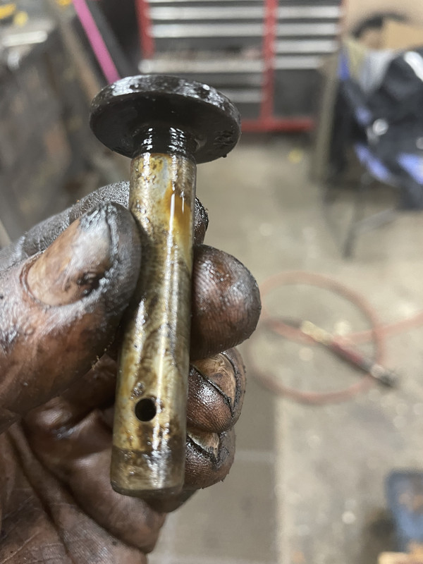 And here you go - all disassembled. One Model T engine block (cracked) which is good for scrap. 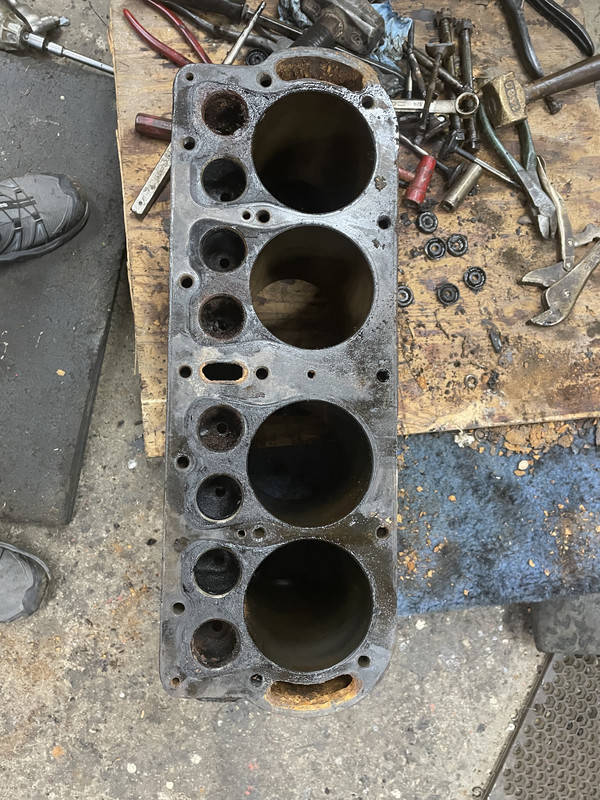 Taking inventory of what can be salvaged, the answer is "not much". Block is scrap. Two of the connecting rods are bent. Crank is scored at the front main. The front main bearing is on the far left in the pic below. It is pretty trashed 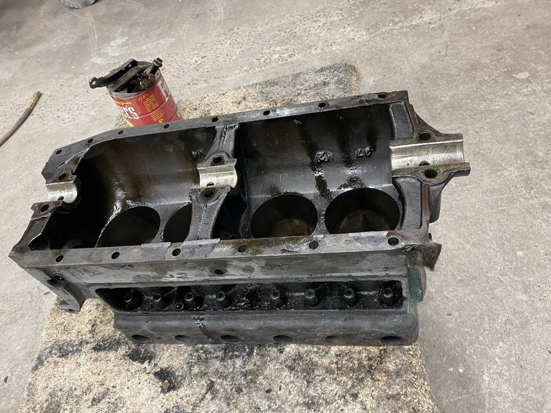 I will be replacing the cam with a 270 lift cam for better breathing. The stock cam is a 250 lift. I will be using all new valves, springs and install adjustable lifters. I will be using a new high compression head. My old transmission may be rebuildable. Have to get the drums magna fluxed to see if they are cracked. But all in all, it looks like I will end up with a brand new engine with a refurbished block and crank. Anybody can tear apart an engine. It takes specialized Model T knowledge and tools to build up a new engine. I lack both. However I have a buddy who is a Model T expert and builds up engines. I will put away tools, clean up, sweep the floor, and maybe learn a thing or two watching him. Pics of the new engine build are up next. |
| Fri Feb 11, 2022 4:11 pm |
|
|
Site Supporter  Location: South Seattle Joined: Thu May 2, 2013 Posts: 12475 Real Name: Steve |
Nice update!
 |
| Fri Feb 11, 2022 5:30 pm |
|
|
Site Supporter Location: Snohomish Co Joined: Thu Sep 13, 2018 Posts: 1811 |
Arisaka wrote: On the back end of the engine, where it meets the transmission, there is a oil tube that carries oil from the transmission to the front main bearing. If this tube gets plugged, you will melt the front main bearing. For this reason, many people plumb a second, external, copper line from the transmission to the front bearing. I had one on my old engine, and will put one on my new engine. Cheap insurance. The oil tube comes out and the magneto coil assembly is unbolted and removed I'm not familiar with that and i have huge gaps in my model t knowledge since i've never owned one with an original drivetrain, but that feels like one of those old timer tricks, that i feel is a non-detergent oil era thing. Kinda like an olds 303 that i have that had the rocker arms drilled and tapped for some 1/8" copper lines to help oil them. Not saying, dont do it, it is obviously an improvement to have extra oil, just kinda airing my thoughts. For those of you wondering what i'm talking about, prior to the 1950's most oils would sludge up and cake the insides with a thick coat of old nasty grease. It has a really distinct sweet smell. I was out in my shop tonite working and can still smell it off the 3 flathead fords i tore down a few months back. |
| Fri Feb 11, 2022 10:54 pm |
|
|
Site Supporter Location: Tacoma Joined: Sat May 4, 2013 Posts: 6214 |
Knowing I would need a new block, a couple months ago I had a used block and a crank sent to the machine shop.
 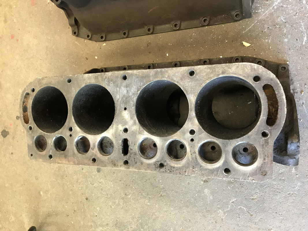 The block got the bores machined out to 0.030” over, and machined for hardened valve seats. The shop pressed in the valve seats and then decked the block. Here you can see the hardened seats in the block 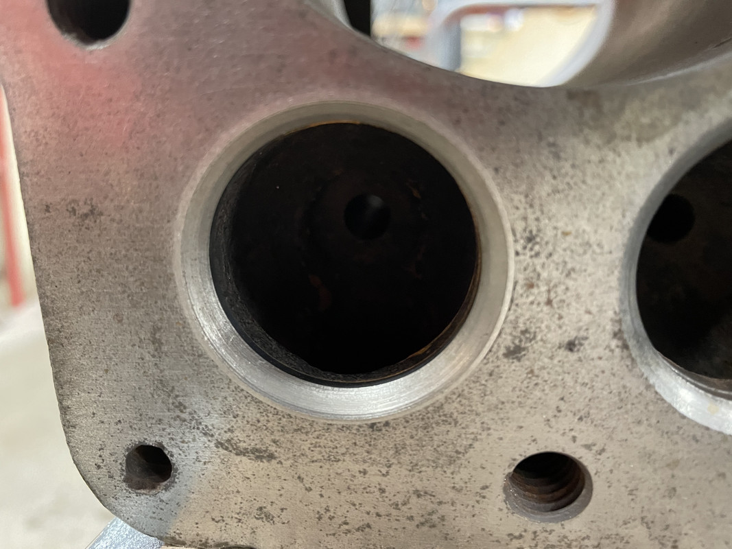 My old block also had hardened seats, but for some reason they were installed too deep - below the surface of the head. And, of course, they were cracked. 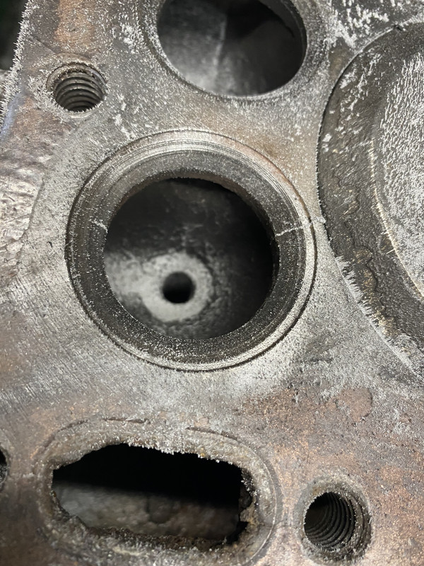 The crank was ground to 0.020” under to clean up scoring in the main and rod journals. This has to be done before babbit because the babbit is custom fit to the block and crank. Next, the block, crank, connecting rods and all the bearing caps were sent to a babbit guy. He cast the babbit in the mains and caps, making sure it was thick enough to final machine to size. Here are the main bearing caps prior to babbit 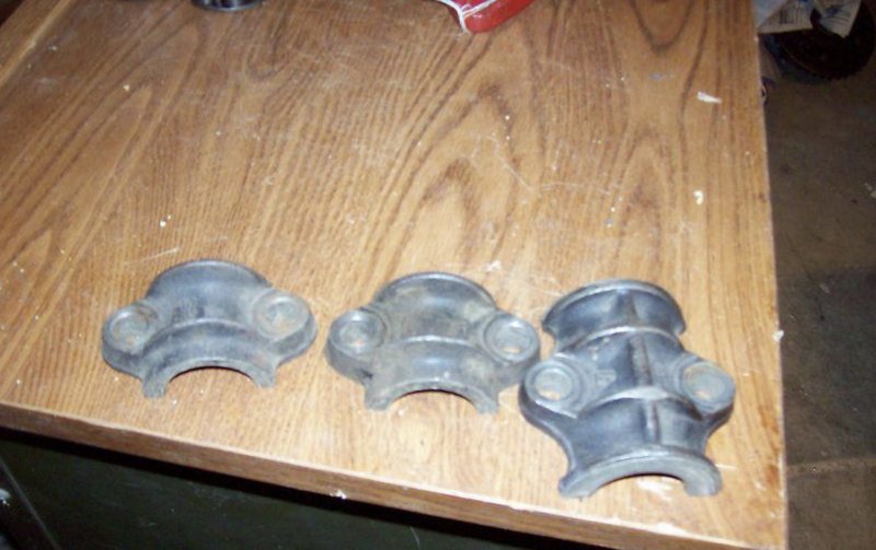 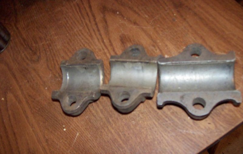 After casting, the block is line bored to fit the crank’s main bearing journals, with 0.0015 clearance. 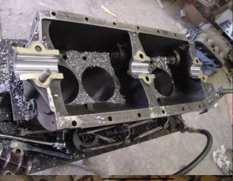 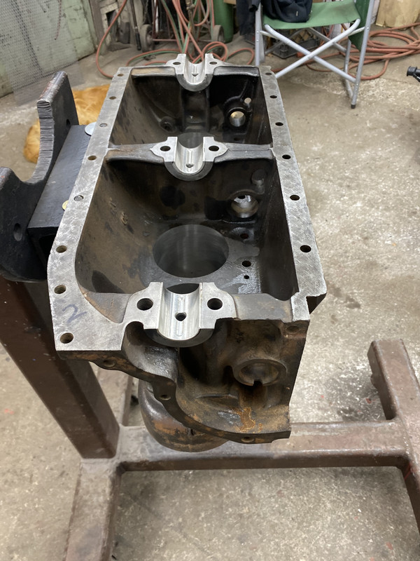 Here is the rear main bearing. Like all the mains, it incorporates a hole and groove for better oiling of the bearings 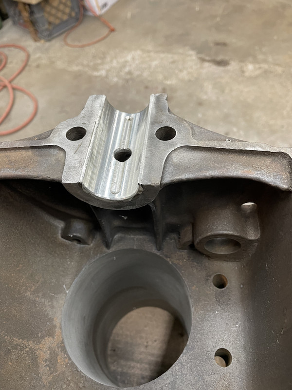 Center main 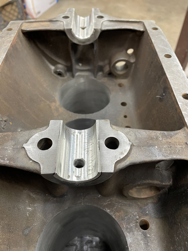 Here is the crank sitting in the block after line boring 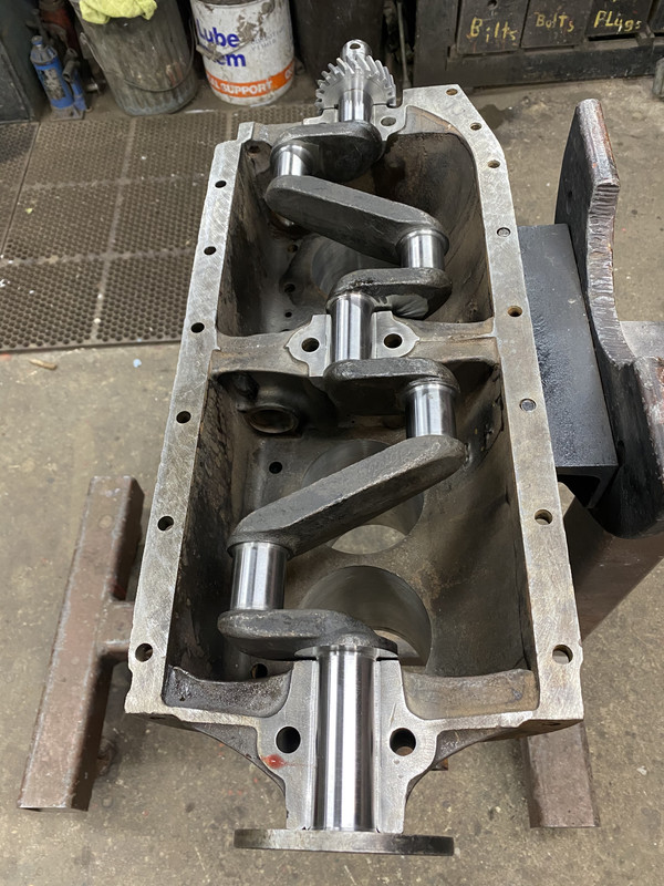 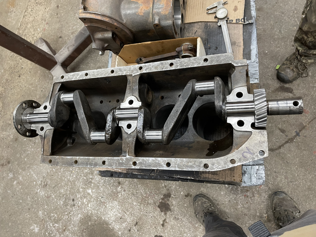 The connecting rods are cast next, and each one machined to fit the rod journals, again with 0.0015 clearance. A shim pack is inserted before machining inside diameter 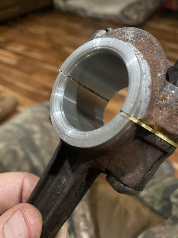 At this point the new block is ready for assembly, which is coming up next |
| Mon Feb 14, 2022 3:04 pm |
|
|
Site Supporter Location: South Seattle Joined: Thu May 2, 2013 Posts: 12475 Real Name: Steve |
Arisaka wrote: At this point the new block is ready for assembly, which is coming up next |
| Mon Feb 14, 2022 7:02 pm |
|
|
Site Supporter Location: Tacoma Joined: Sat May 4, 2013 Posts: 6214 |
Block assembly starts with checking the fit of the bearing end caps. If the babbit guy did his job right, the main bearings are the correct diameter to fit the crank and the rear main bearing cap thrust surface provides 0.004" of crank endplay. Its interesting that the rear main cap provides the entire thrust surface. The rear main bearing in the block has no thrust surface.
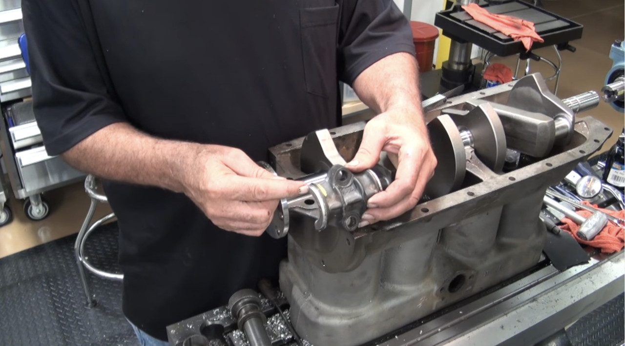 Also, all the mains must be radiused to clearance the radius in the crank. 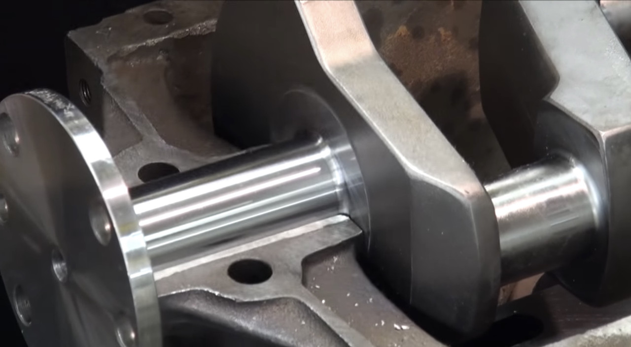 The correct bearing to crank fit is checked by pre-assembly of the bearing caps, torquing the main bolts to 55 ft-lbs, and spinning the crank to ensure it rotates freely. If it hangs up you can use a lapping compound to cut the babbit and allow free rotation. When the bearings are good to go, crank installation begins with assembly lube on the main bearings and then dropping in the crankshaft 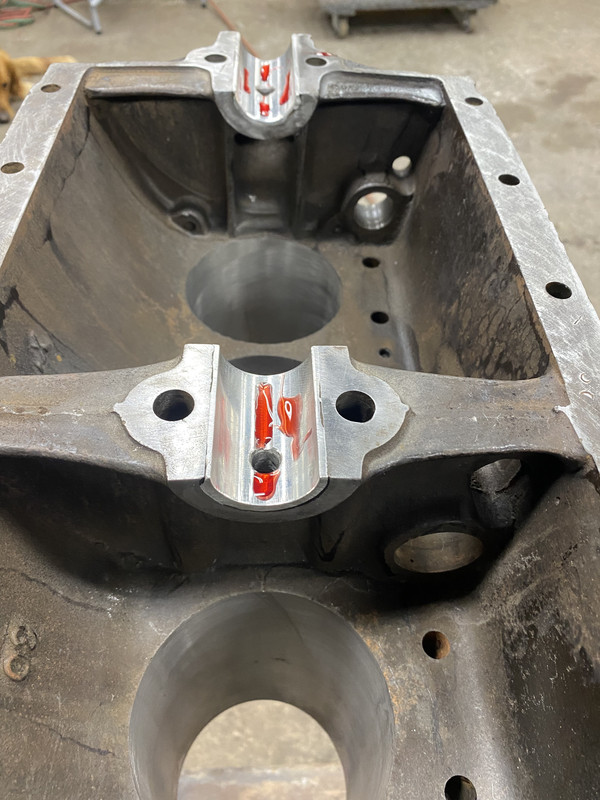 Caps are torqued to 55 ft-lbs 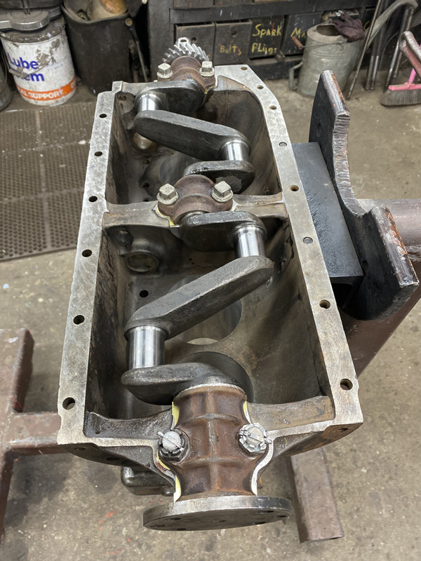 The cam bearings are then fit to the cam and the block using a lathe as necessary, and the cam bearings installed on the cam. Here is a cam bearing. The hole in the side of the bearing interfaces with a bolt going through the block. That bolt keeps the cam bearing from rotating in the block. 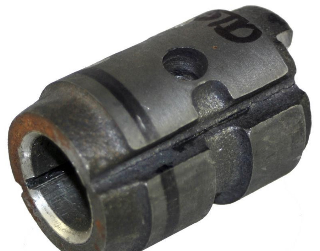 Here is the front cam bearing installed on the cam. There is a similar center cam bearing.  There is also a cam bushing in the rear of the block that must be reamed to fit and pressed into the block. The cutout in the bushing faces up so oil splash from the flywheel is captured and routed to the cam. 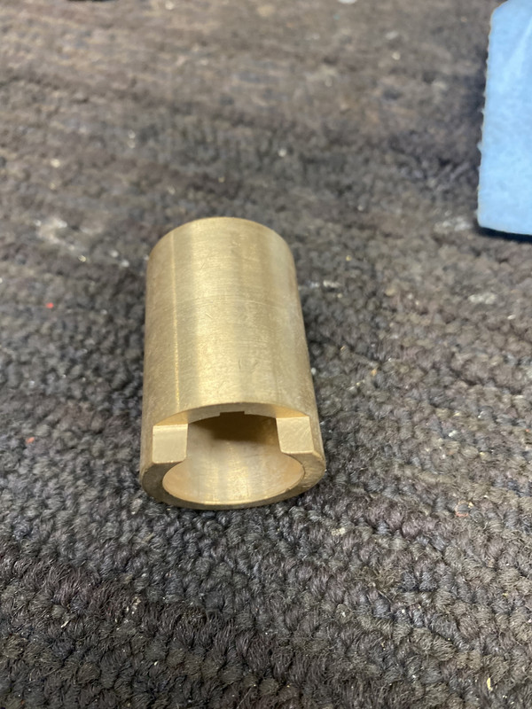 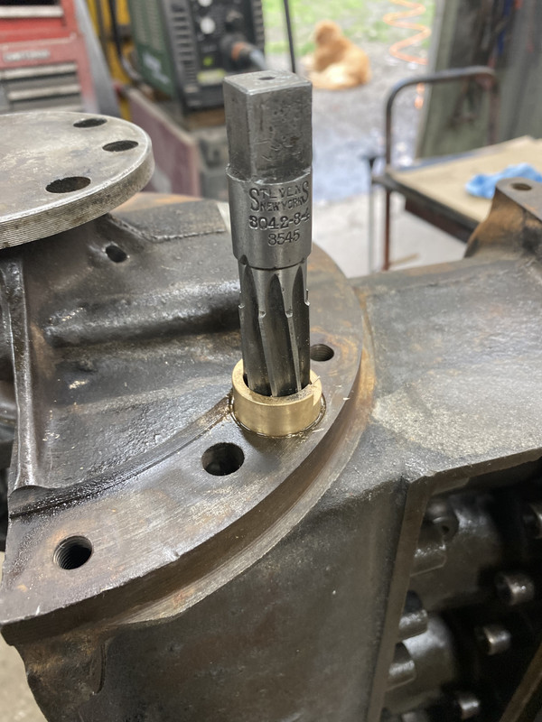 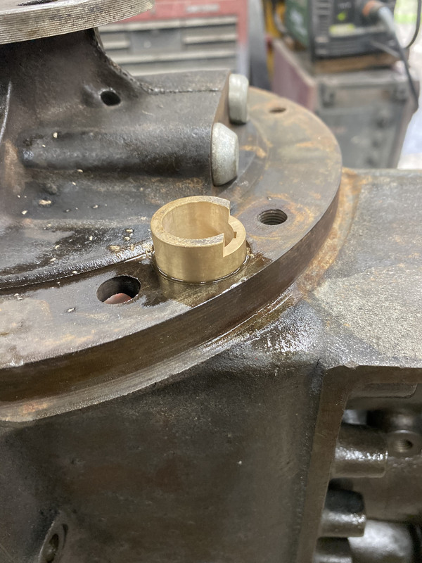 The lifters are dropped in. The head of the lifter rides on the cam lobe, and so moves up and down. That stem of the lifter contacts the stem of the exhaust and intake valves. This way, the up and down motion is translated to the valves, moving them up and down. I am using adjustable lifters. Original lifters were not adjustable, so valve gap was set by grinding off some of the valve stem. Adjustable lifters are much easier to work with. Here are pics of the original style, and the adjustable lifters 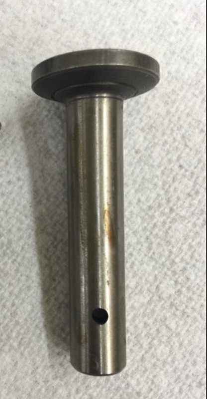 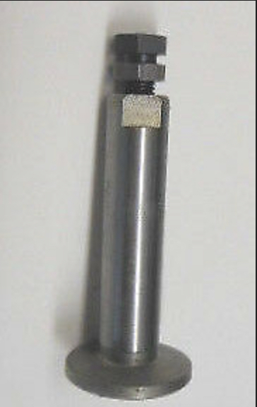 The cam is slid in from the front of the engine, and the timing gear meshed with the crank gear. Original timing gears were steel. I am using a brass timing gear, as they run quieter. 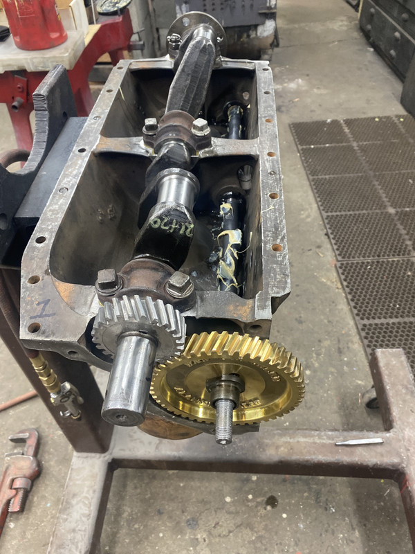 The connecting rod bearing fit is now checked to ensure free rotation on the crank. Here are the connecting rods 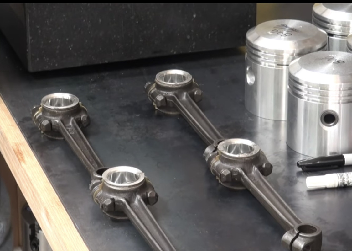 Piston rings are fit into the bores to check end gap. Looking for 0.004" end gap per inch of bore diameter, or about 0.015" total. 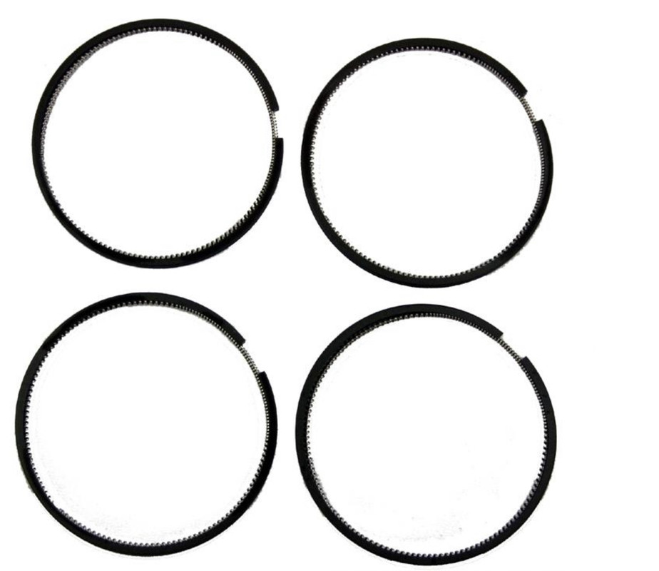 With the piston ready, the connecting rod is attached to the piston by the wrist pin. The wrist pin is rigidly clamped to the connecting rod by a bolt. All the rotation is between the wrist pin and the piston bushings, so that fit up must rotate smoothly. If the fit is too tight, the piston will rise in the bore cocked at an angle, and scuff the piston skirt. Here is the wrist pin. The groove in the pin is clearance for the connecting rod bolt that clamps the connecting rod to the wrist pin 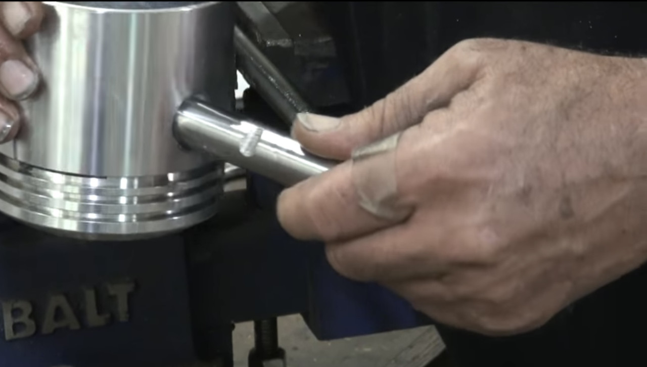 The piston has an oil hole in one side. That oil hole must face away from the cam when the piston is installed, in order to collect oil  A ring compressor is used to install the pistons, just as in modern engines. The connecting rod is guided onto the crank and the cap installed. Unique to a Model T are oil dippers on each connecting rod cap, something Ford added at the end of the Model T production run to improve oiling. The dipper faces the cam. Its job is to collect oil on the downstroke of the piston, and then fling it around. There is no oil pump on a Model T. All lubrication relies on oil being splashed everywhere. Here is what the dippers look like 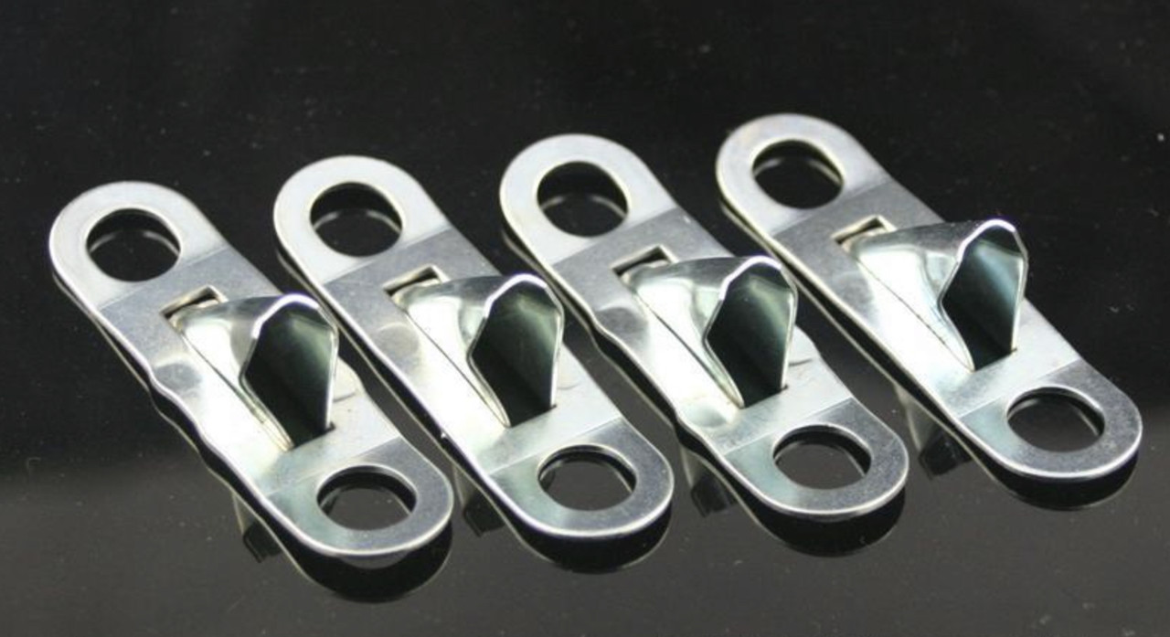 Here is the completed bottom end, with the connecting rods and dippers installed 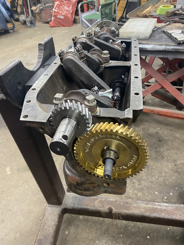 Next up are the valves Last edited by Arisaka on Thu Mar 03, 2022 8:55 am, edited 1 time in total. |
| Sat Feb 26, 2022 10:43 am |
|
|
Site Supporter  Location: Everson, WA Joined: Sun Jan 6, 2013 Posts: 28178 Real Name: Ace Winky |
My brother has my grandpa's T. I have never seen a model T engine so clean.
_________________ Why does the Penguin in Batman sound like a duck? Because the eagle sounds like a hawk. |
| Sat Feb 26, 2022 2:58 pm |
|
|
Site Supporter Location: South Seattle Joined: Thu May 2, 2013 Posts: 12475 Real Name: Steve |
Great Pics & Info, as usual
|
| Sat Feb 26, 2022 3:56 pm |
|
|
Site Supporter Location: Tacoma Joined: Sat May 4, 2013 Posts: 6214 |
Model T valves are interesting. They are not single-piece valve as you would expect. Rather, to save money, Ford used a steel stem with a cast iron head. The stem was placed in a mold, and then the molten cast iron poured in. Here is what they look like
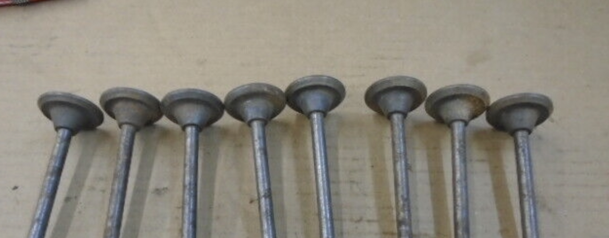 Here is a cutaway view. The two holes in the valve head are for inserting the Ford factory valve lapping tool. 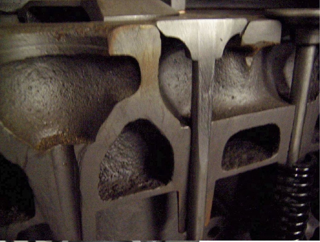 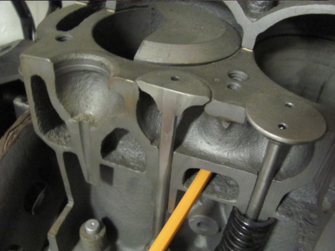 The cast-on valve heads have been known to come off. That usually results in significant damage to the piston, cylinder and/or head. Although some people still run the original valves, most people switch to a one-piece stainless steel valve when doing an overhaul. Here are a set of those one-piece stainless valves 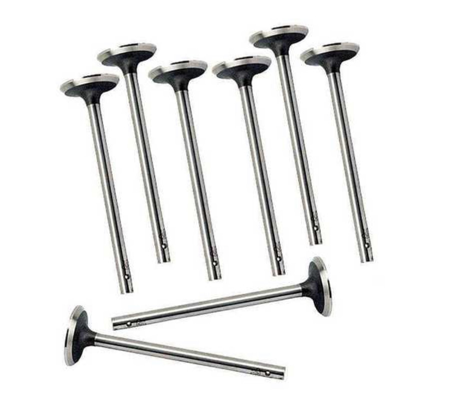 Before you order the valves you have to look at the valve guides. The guides are an integral part of the engine block casting. Since they are cast iron, they frequently wear and must be reamed back round. This is addressed by reaming the valve guides out to either 0.015" or 0.030" over, and buying valves with matching stem diameters. You can go over more than 0.03" if necessary. You can even go way over and put in an insert. But in most cases the guides will clean up at 0.015 or 0.030" over. Here is a valve guide reaming tool 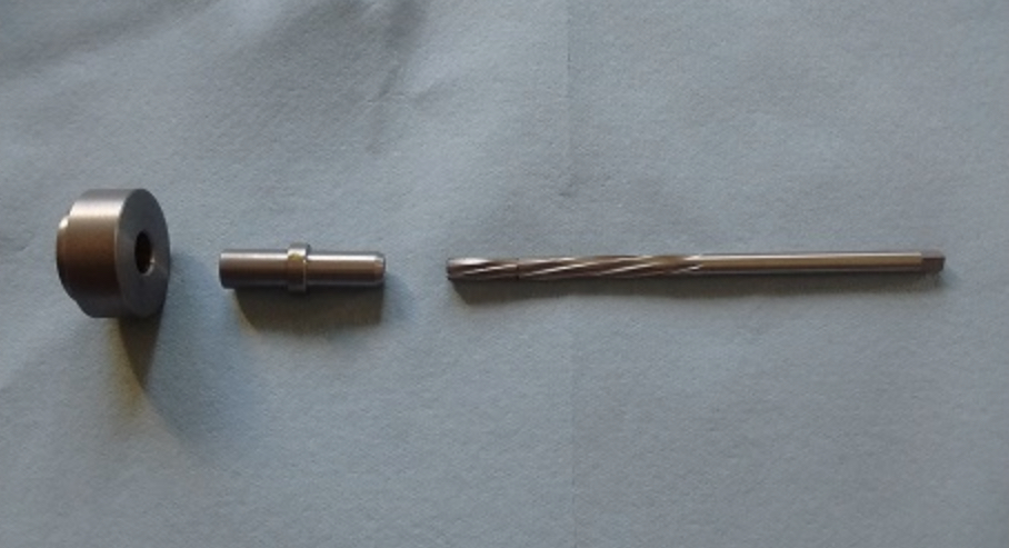 Here it is in action 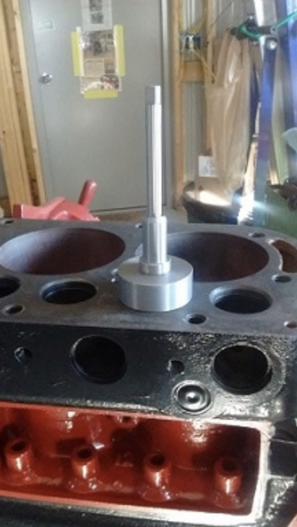 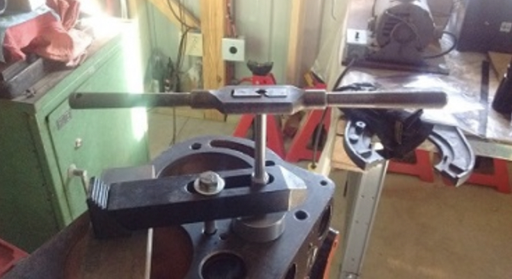 Here is an original valve guide reamer 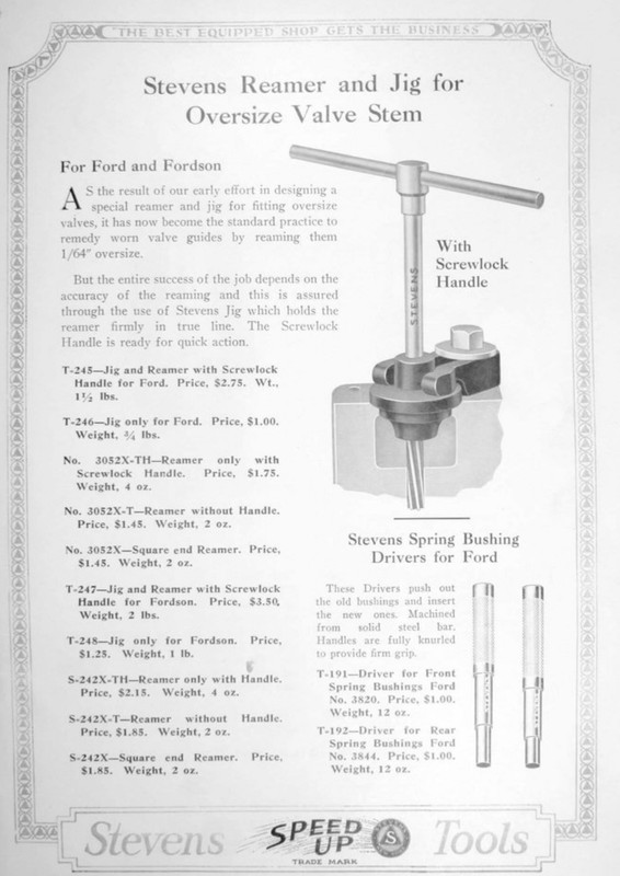 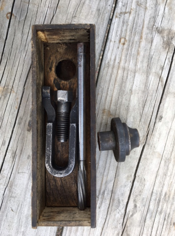 My valve guides had to go 0.015'" over. So I bought valves with stem diameter 0.015" over. The first step in installing each valve is to turn the engine over so the lifter is all the way down. With original lifters, you now drop in the valve, and grind off the stem until you get the desired gap/clearance/lash. For original valves that was 0.022", or "one thin dime". For the one-piece valves, lash is 0.010 to 0.015. You repeatedly install, measure, remove and grind off the valve stem until you get the desired lash. It takes a lot of time, because if you take too much off you will be buying another valve. A more convenient approach is to use adjustable lifters. Here are original, and adjustable lifters With adjustable lifters, you first crank the adjuster down as far as you can, to get a large gap between the lifter and the valve. Then you check to make sure the valve is fully seated. If its seated it won't rotate. With the valve seated, you use wrenches to move up the adjuster to reach desired lash. My valves are set at 0.013-0.014" lash. Here is a pic off the internet showing how that is done 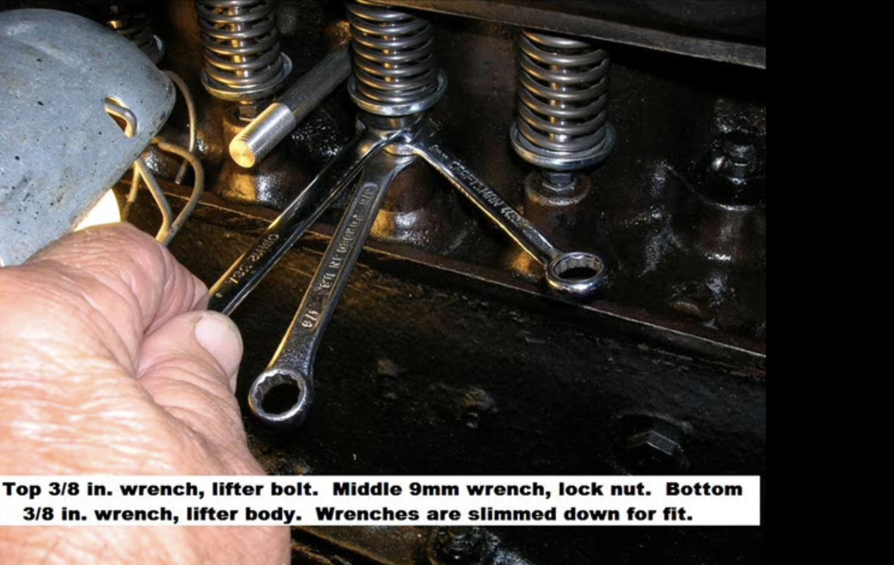 Once lash is set on all 8 valves, it is time to do final installation. The valve springs, seats and cross-pins are assembled. Here is what those look like 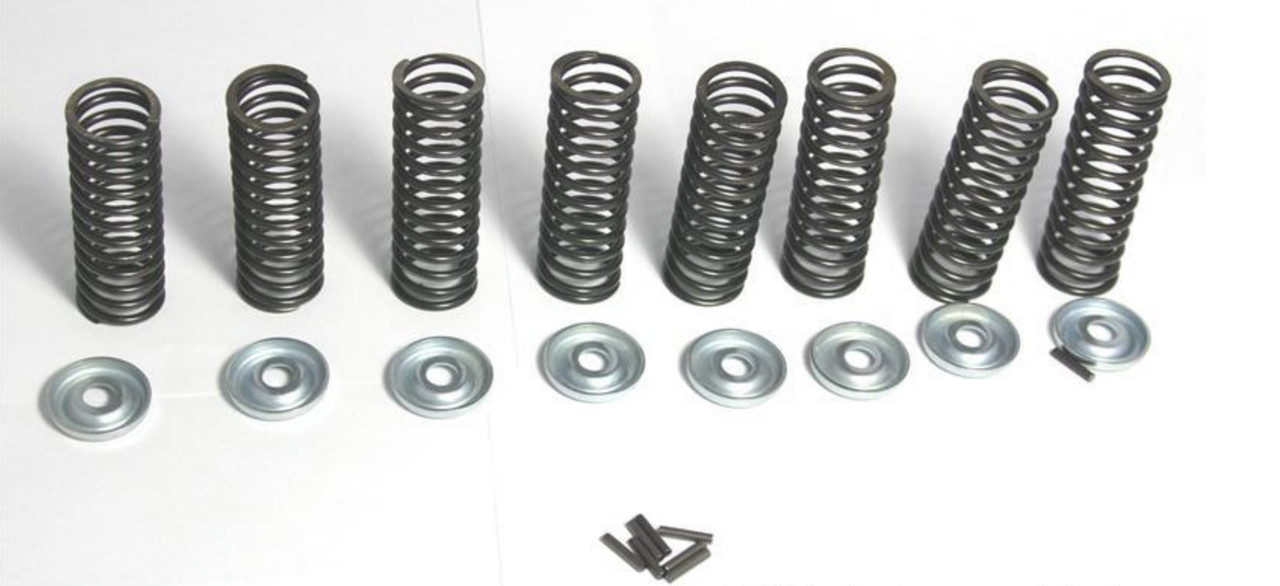 The seat is placed under the spring, and the assembly squeezed into place over the lifter 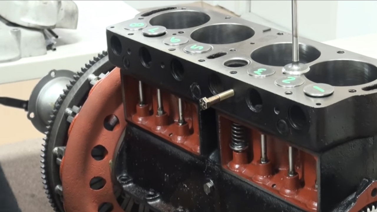 The valve stem and guide are oiled, and the valve dropped in. The valve is rotated so you will be able to access the hole in the stem for the cross-pin. 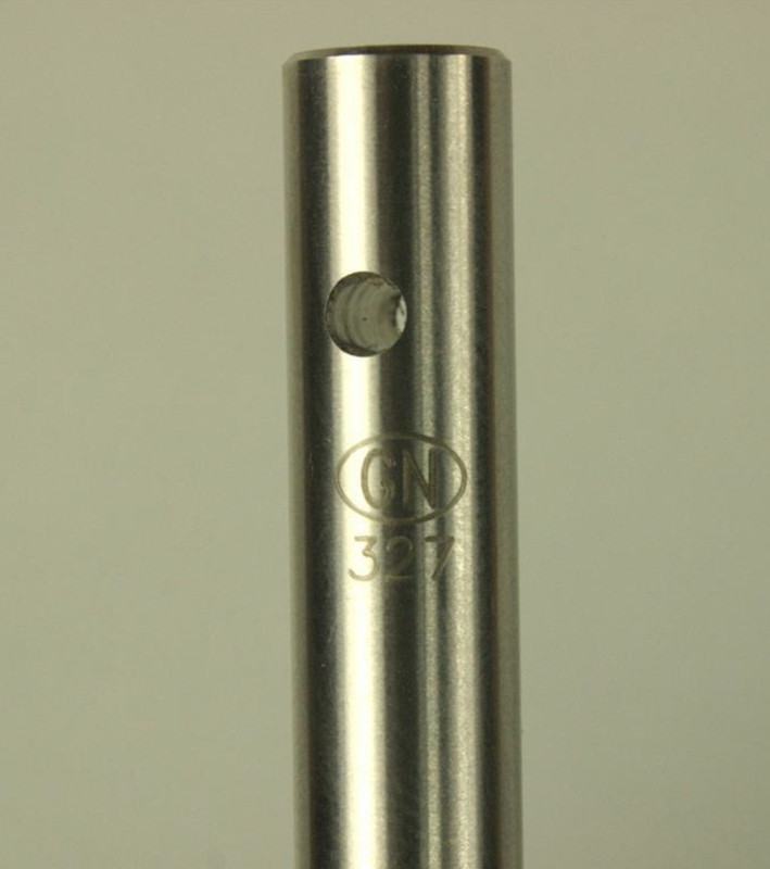 A spring compressor is used to compress the 24 lb. valve springs Then the cross pin is installed 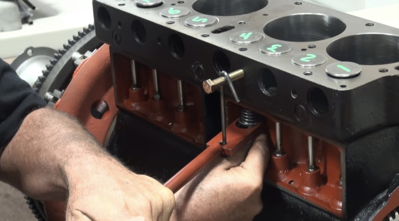 You do this 7 more times and you are done. Then you re-check lash to make sure nothing has moved. Next up is the Ford transmission, Last edited by Arisaka on Wed Mar 02, 2022 5:20 pm, edited 2 times in total. |
| Wed Mar 02, 2022 5:13 pm |
|
|
Site Supporter Location: Everson, WA Joined: Sun Jan 6, 2013 Posts: 28178 Real Name: Ace Winky |
Whoa.
_________________ Why does the Penguin in Batman sound like a duck? Because the eagle sounds like a hawk. |
| Wed Mar 02, 2022 5:15 pm |
|
|
Site Supporter Location: South Seattle Joined: Thu May 2, 2013 Posts: 12475 Real Name: Steve |
Very cool!
|
| Wed Mar 02, 2022 7:37 pm |
|
|
Site Admin   Location: Renton, WA Joined: Sun Mar 13, 2011 Posts: 52035 Real Name: Steve |
Damn. We're gonna have to put a binder on this thread and start selling books.
_________________ Steve Benefactor Life Member, National Rifle Association Life Member, Second Amendment Foundation Patriot & Life Member, Gun Owners of America Life Member, Citizens Committee for the Right to Keep and Bear Arms Legal Action Supporter, Firearms Policy Coalition Member, NAGR/NFGR Please support the organizations that support all of us. Leave it cleaner than you found it. |
| Wed Mar 02, 2022 8:28 pm |
|
|
Site Supporter Location: Tacoma Joined: Sat May 4, 2013 Posts: 6214 |
The Model T transmission is the least understood part of the car. I know it confuses me. Basically, the Model T has two forward speeds, a neutral and a reverse gear. To engage low speed, you push the low speed pedal all the way to the floor. When you get up to speed, you let the pedal all the way up and the transmission is now in high speed. High speed is direct drive, i.e. the transmission is rotating at the same speed as the engine. To find neutral, you push the pedal half way down and hold it there. Or you can pull the emergency brake lever back halfway. To engage reverse, you push down the reverse pedal. The only other pedal is the brake pedal. But, the brake is a transmission brake. There are no brakes on the front axle, and only the emergency brake on the rear axle.
So, enough of that. Here is what a Model T transmission looks like. 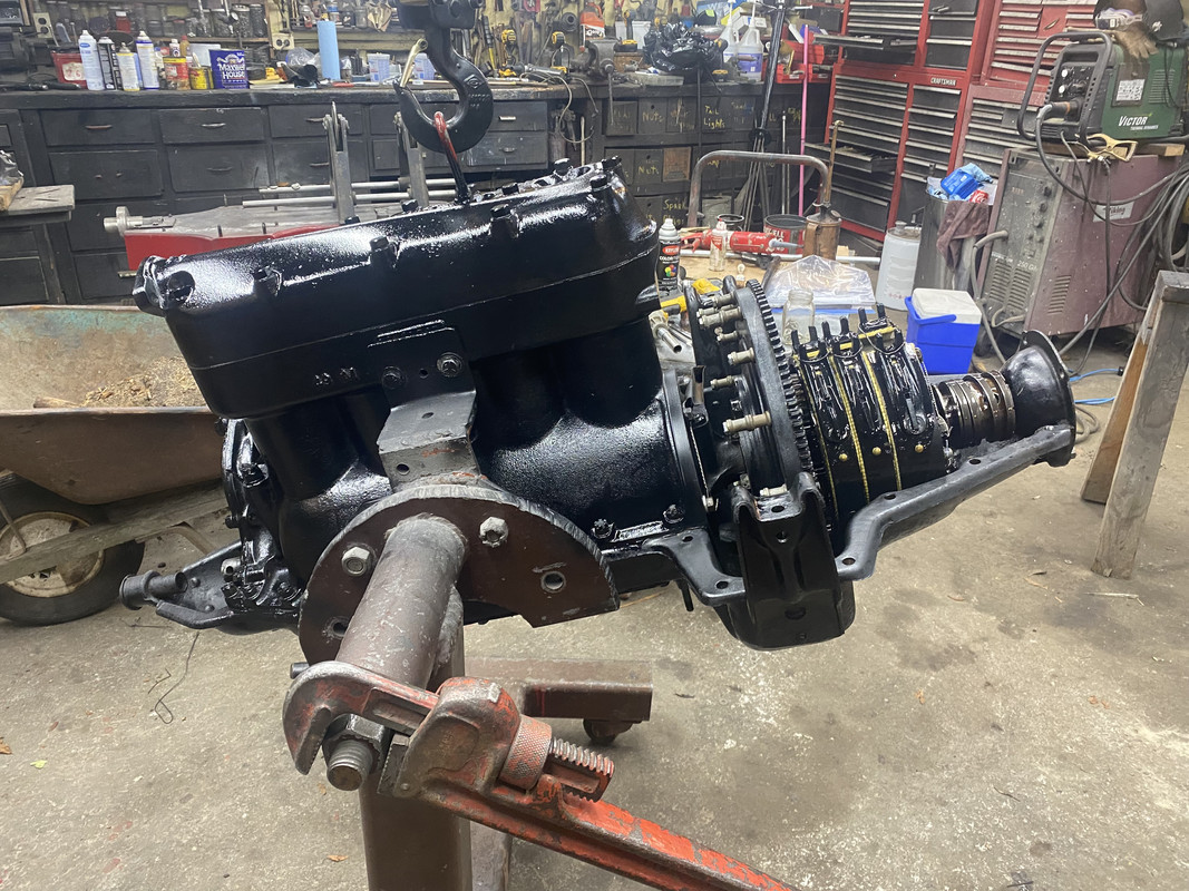 It is around 90 lbs of spinning drums and gears. Ford didn't bother to balance any of the spinning components, so it vibrated quite a bit. Today, people balance the bigger spinning parts, such as the reverse, low speed and brake drums, and the flywheel. Here are the major components of the transmission 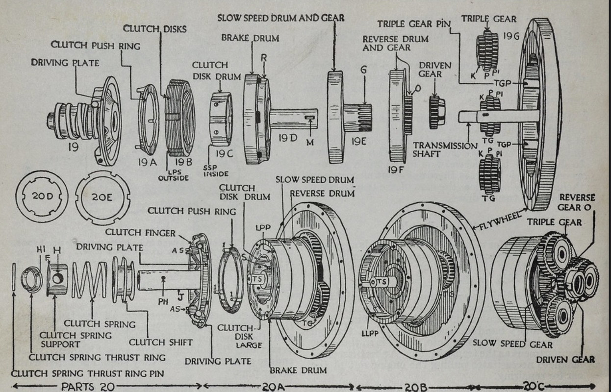 The rebuild starts with preparing the major components for assembly. This consists of checking for cracks by magna fluxing the flywheel and the three drums, and inspecting each for good gear teeth and a smooth outer surface. Then all the bushings are replaced. Here is a full transmission bushing set for a Model T 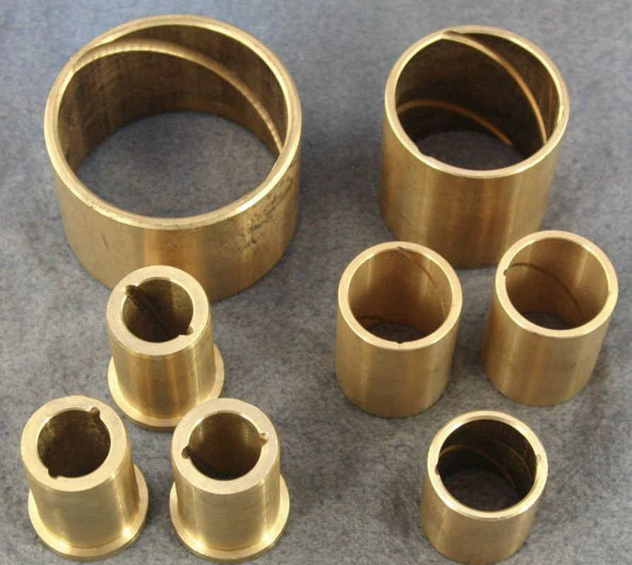 The standard flywheel contains the magneto assembly, which is a set of magnets that rotate next to field coils. This generates electricity for the engine. Later Model T's also had a generator which charges the battery, with the battery then providing electricity for the engine. I won't be using a magneto. Eliminating it removes a lot of rotating mass, and since I am running a distributor and 6V modern coil, the magneto wouldn't work for me anyway. Here is what the magneto looks like. The first pic is the flywheel with v-shaped magnets mounted on it. The second pic is the field coil assembly. The last pic is the assembled magneto 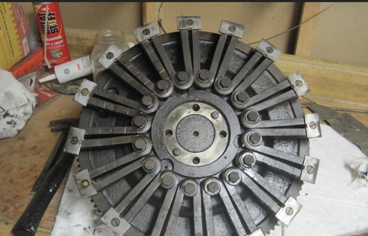 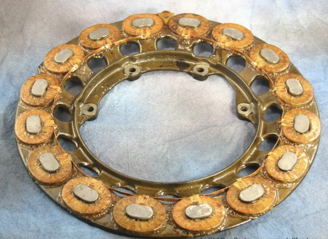 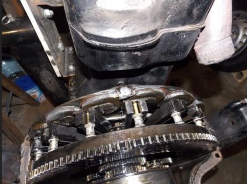 Back to my build, the first job is to balance the flywheel. This is done on a precision tool, that costs a few bucks. Here is the flywheel being balanced. To balance it, you dimple the heavy area with a 1/2" drill to remove metal. 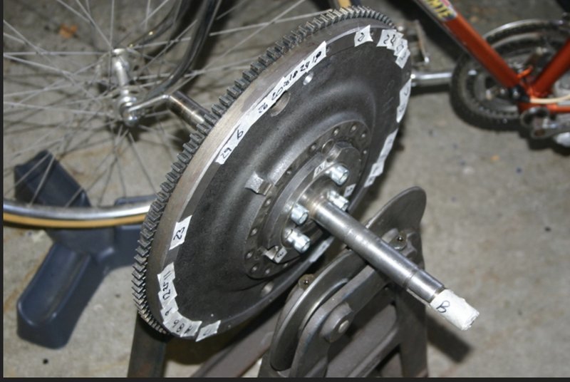 The main transmission shaft is checked for runout, and then bolted to the flywheel 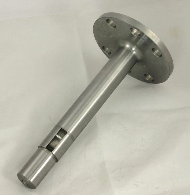 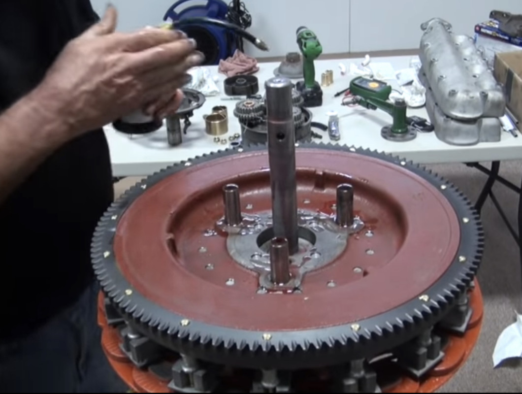 Now the brake drum, low speed drum and reverse drum are balanced The brake drum is balanced the same way as the flywheel - dimple drill the web until the drum is balanced. Here is a brake drum being balanced, and with a dimple being drilled into the web 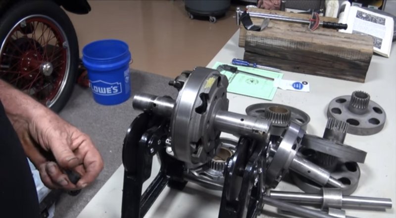 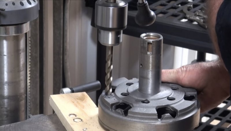 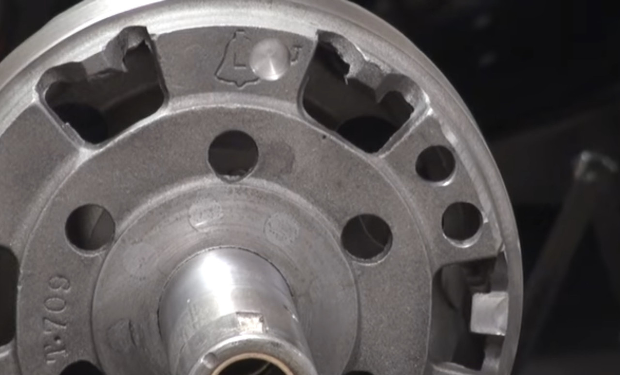 The low speed and reverse drums have thinner webs than the brake drum, so the best way to balance them is to drill a through-hole in the web on the light side, and install a nut and bolt and washers as necessary to add weight. And use locktite. 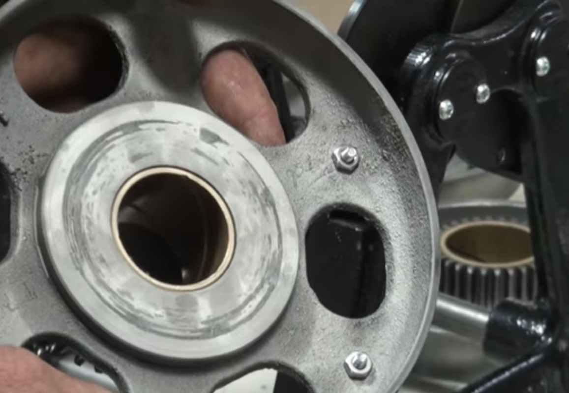 Next up is assembly of the transmission Last edited by Arisaka on Tue Mar 08, 2022 11:17 pm, edited 2 times in total. |
| Tue Mar 08, 2022 12:47 pm |
|
|
Site Supporter Location: South Seattle Joined: Thu May 2, 2013 Posts: 12475 Real Name: Steve |
Interesting
|
| Tue Mar 08, 2022 8:54 pm |
|
|
Site Admin Location: Renton, WA Joined: Sun Mar 13, 2011 Posts: 52035 Real Name: Steve |
Is that how they balance tires, too?
 Fascinating info, Arisaka. I had no clue about any of this. _________________ Steve Benefactor Life Member, National Rifle Association Life Member, Second Amendment Foundation Patriot & Life Member, Gun Owners of America Life Member, Citizens Committee for the Right to Keep and Bear Arms Legal Action Supporter, Firearms Policy Coalition Member, NAGR/NFGR Please support the organizations that support all of us. Leave it cleaner than you found it. |
| Wed Mar 09, 2022 5:55 am |
|
|
|
Page 24 of 31 |
[ 454 posts ] | Go to page Previous 1 ... 21, 22, 23, 24, 25, 26, 27 ... 31 Next |
|
All times are UTC - 8 hours |
Who is online |
Users browsing this forum: No registered users and 35 guests |
| You cannot post new topics in this forum You cannot reply to topics in this forum You cannot edit your posts in this forum You cannot delete your posts in this forum You cannot post attachments in this forum |