WaGuns.org https://www.waguns.org/ |
|
1926 Model TT Restoration: Engine/Trans Rebuild https://www.waguns.org/viewtopic.php?f=148&t=98621 |
Page 17 of 31 |
Author: | Arisaka [ Sat Feb 01, 2020 7:36 pm ] |
Post subject: | Re: 1926 Model TT Restoration: Boom Truss Fab |
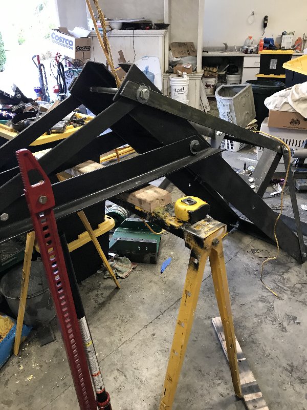
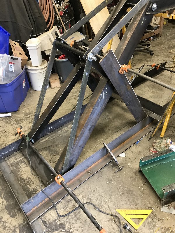
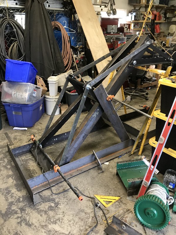
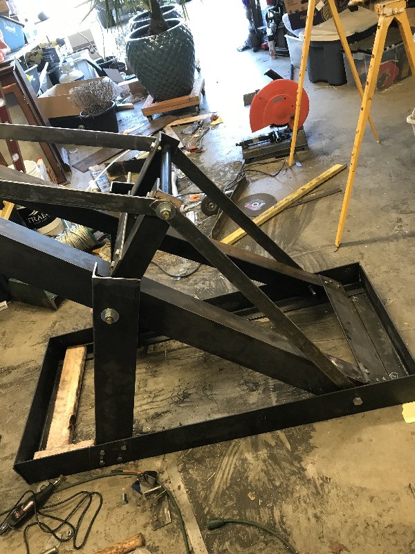
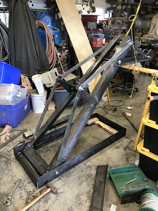
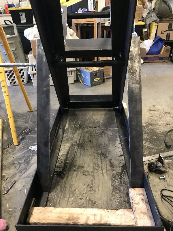
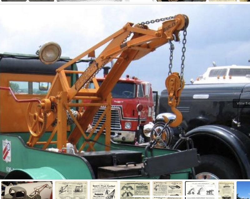
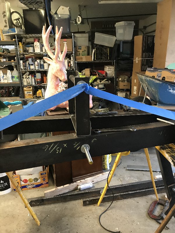
Finished up the boom truss today. This is the suspension bridge looking assembly perched on top of the main boom 
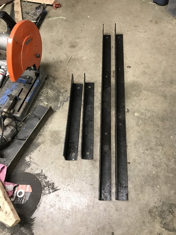
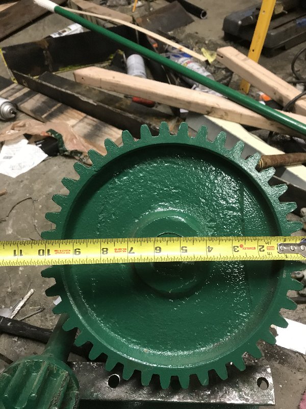
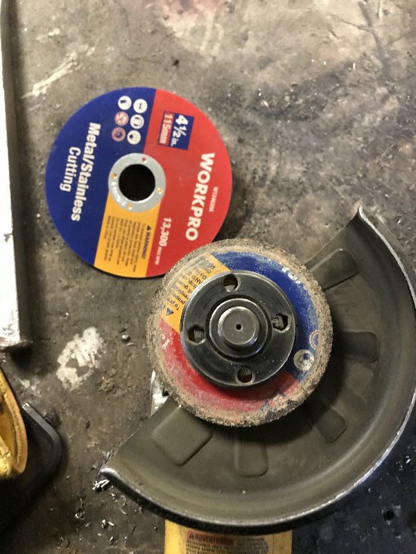
The support tower is centered on the boom pivot. It consists of one piece running across the boom, and two pieces sticking up on each end. I fabbed these pieces from my hoard of 3 x 5 angle iron using a 4 1/2” angle grinder and many cutting discs. 
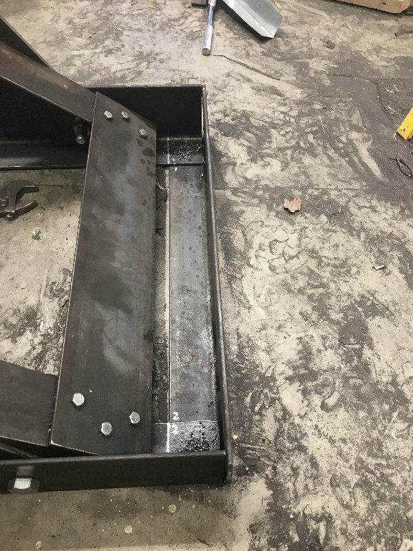
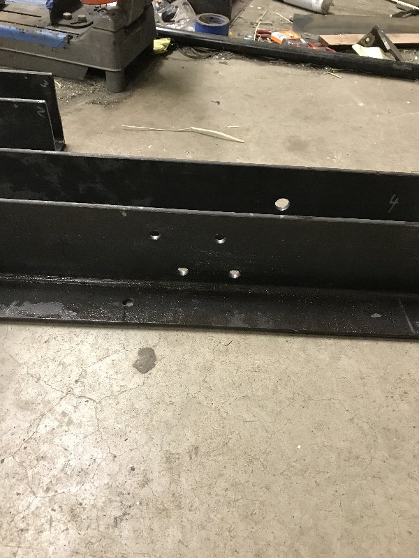
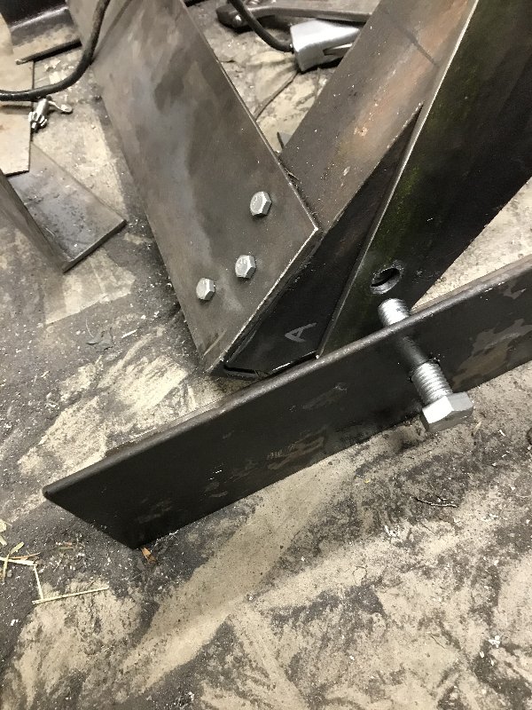
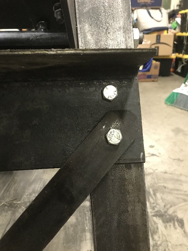
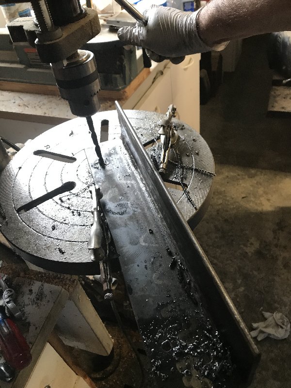
Drilled holes for 1/2” bolts 
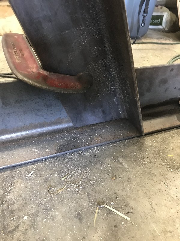
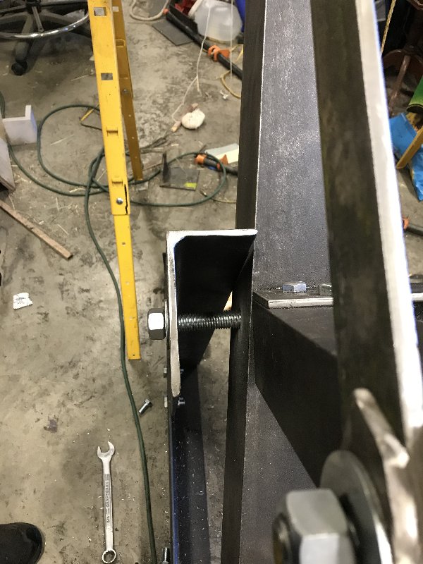
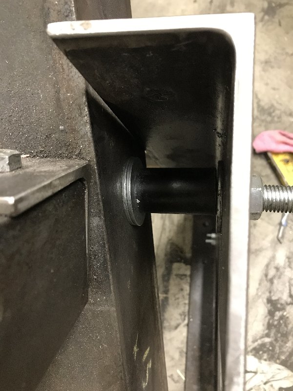
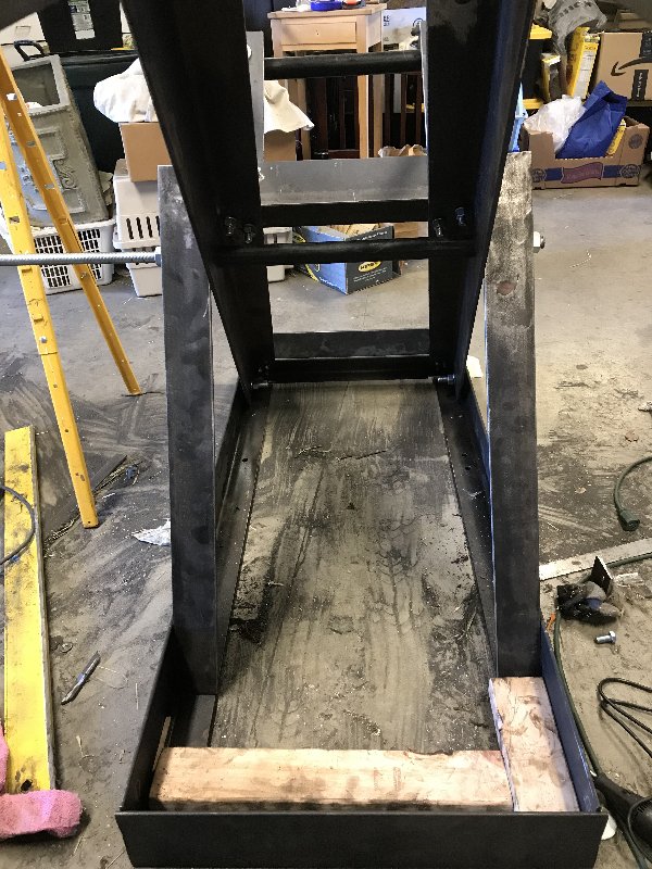
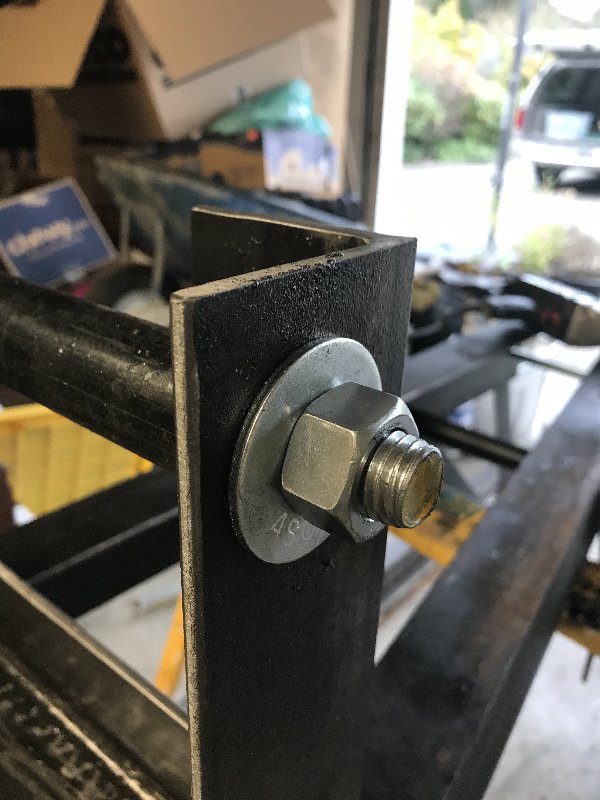
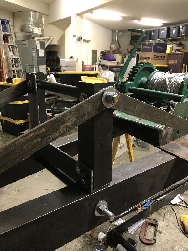
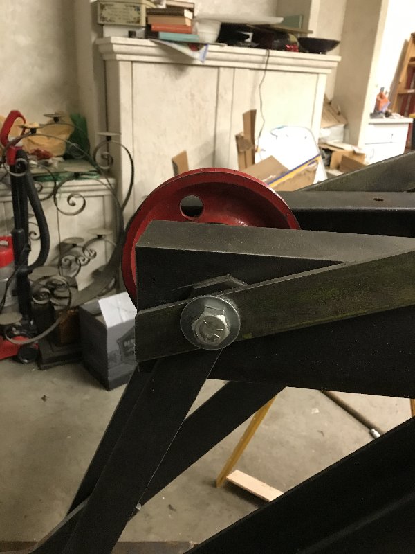
The three pieces of angle were then bolted together with 1/2” bolts, with more 1/2” bolts attaching the tower to the main boom. The two vertical legs are joined with a 3/4” threaded rod inside of a piece of 1” black iron pipe, and torqued down with big old 3/4” nuts 
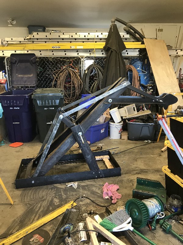
I used some painters tape to simulate the suspensign arms, in order to check the tower height. It looked like a pretty good match to the original crane’ 
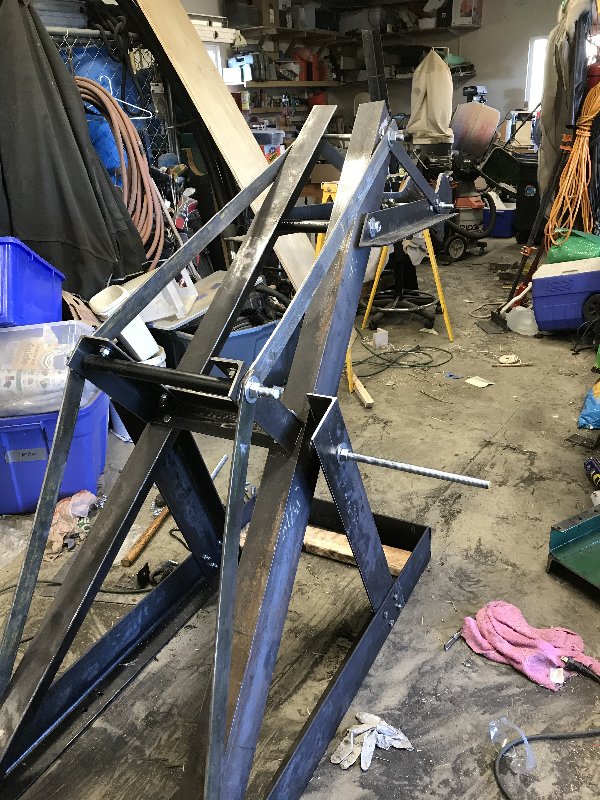
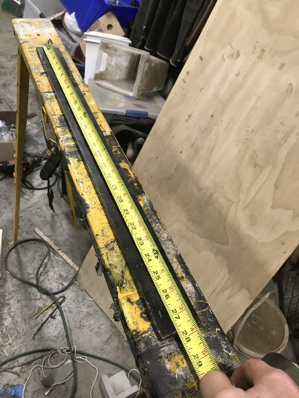
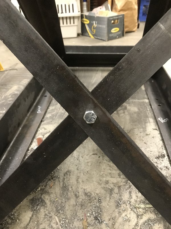
Now I had to cut 42” long suspension arms to join both ends of,the boom to the tower. Back to my stash of angle iron, this time to cut out 2” wide x .25” x 42” arms. Needed four of these. That’s about 16 feet of .25 inch steel cut with a 4.5” angle grinder. It was not fun. 
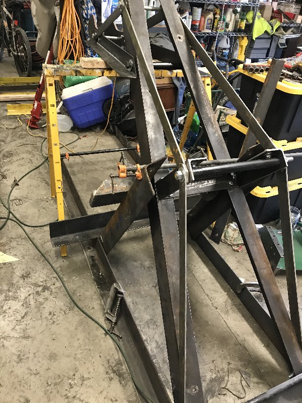
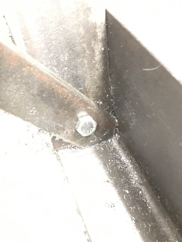
Drilled 3/4” holes in both ends of the arms. Needed matching holes at the base of the boom. Then I attached all 4 arms 
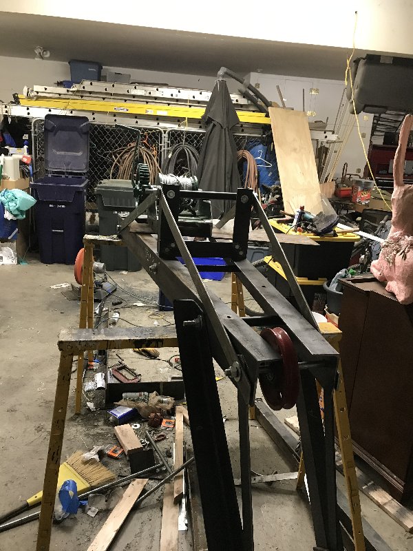
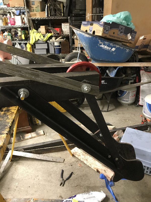
This whole truss assembly is massive overkill, but that’s how they used to make them. Next up is the support cradle for the boom, followed by positioning and mounting the winch |
Author: | Pablo [ Sun Feb 02, 2020 5:24 am ] |
Post subject: | Re: 1926 Model TT Restoration: Boom Truss Fab |
Where is the LIKE button? |
Author: | RocketScott [ Sun Feb 02, 2020 8:07 am ] |
Post subject: | Re: 1926 Model TT Restoration: Boom Truss Fab |
That's looking sweet! Probably better built than the originals were |
Author: | Traut [ Sun Feb 02, 2020 11:03 am ] |
Post subject: | Re: 1926 Model TT Restoration: Boom Truss Fab |
You're going to need another boom truck to lift that behemoth! Looking good! |
Author: | Arisaka [ Sun Feb 02, 2020 11:40 am ] |
Post subject: | Re: 1926 Model TT Restoration: Boom Truss Fab |
Traut wrote: You're going to need another boom truck to lift that behemoth! Looking good! You are right. I expect it to weigh upwards of 500 lbs when done. Which is why this crane model was only mounted on the big 1 ton trucks. I will have to take it apart and build it back up in the bed of the truck. |
Author: | usrifle [ Sun Feb 02, 2020 12:16 pm ] |
Post subject: | Re: 1926 Model TT Restoration: Boom Truss Fab |
Arisaka wrote: Traut wrote: You're going to need another boom truck to lift that behemoth! Looking good! You are right. I expect it to weigh upwards of 500 lbs when done. Which is why this crane model was only mounted on the big 1 ton trucks. I will have to take it apart and build it back up in the bed of the truck. Very Cool, and now we know why you needed the High Compression head/extra power from the engine. To haul that Boom! |
Author: | RocketScott [ Sun Feb 02, 2020 1:03 pm ] |
Post subject: | Re: 1926 Model TT Restoration: Boom Truss Fab |
Arisaka wrote: Traut wrote: You're going to need another boom truck to lift that behemoth! Looking good! You are right. I expect it to weigh upwards of 500 lbs when done. Which is why this crane model was only mounted on the big 1 ton trucks. I will have to take it apart and build it back up in the bed of the truck. If we can get it out the door I can pick it up and put it in the truck |
Author: | Arisaka [ Sun Feb 02, 2020 1:08 pm ] |
Post subject: | Re: 1926 Model TT Restoration: Boom Truss Fab |
RocketScott wrote: Arisaka wrote: Traut wrote: You're going to need another boom truck to lift that behemoth! Looking good! You are right. I expect it to weigh upwards of 500 lbs when done. Which is why this crane model was only mounted on the big 1 ton trucks. I will have to take it apart and build it back up in the bed of the truck. If we can get it out the door I can pick it up and put it in the truck When I get it done, I can put a tow strap on it and drag it out onto the driveway. The boom truck will make short work of lifting it! Thanks Scott! |
Author: | RocketScott [ Sun Feb 02, 2020 4:53 pm ] |
Post subject: | Re: 1926 Model TT Restoration: Boom Truss Fab |
Anytime. I have a stack of siding behind it right now but that should be used up soon |
Author: | Arisaka [ Mon Feb 10, 2020 6:14 pm ] |
Post subject: | Re: 1926 Model TT Restoration: Cradle Fab |
Finally got the cradle done. The cradle supports the boom at a 45 degree angle. It is built from angle iron. First step was to cut two long arms and two short arms. Here is what they look like mocked up The next job was to orient the boom at a 45 degree angle. Had to use a Hi-Lift jack to get this thing up on a sawhorse. Now to locate the boom in the cradle, and mock up the support arms Time to drill a bunch of holes now. The long arms of the frame were drilled to accept the base of the boom Then the frame is drilled to accept the support arms The support arms join the boom at an angle. That angle was set by what I thought looked good. I mocked it up, got it where I wanted it and used a bevel gauge to mark the cut line on the support arms. Then the support arms were match-drilled to the frame. The last drill jobs were holes to mount the frame to the bed of my truck Assembly time! Frame was bolted to the boom with 3/4” grade 5 bolts. Had to drill some of these holes with a monster hand drill, using a 13/16” bit. I inherited this gear-driven drill from my dad. It is a beast and will rip your arm clean off if you bind the bit. Scares the crap out of me. Dad used to own a service station, that burned down. This drill was one of the few things that was salvaged; you can see where the data tag was melted by the fire. Back to work. The support arms were attached with 1/2” grade 5 bolts Next the top of the support arms were drilled to accept the boom pivot. I had to Fab some spacers from 1” pipe as well Here is the whole thing bolted together Next up is to add some cross-bracing to connect the cradle support arms, and then add the rigging and winch. |
Author: | RocketScott [ Mon Feb 10, 2020 8:15 pm ] |
Post subject: | Re: 1926 Model TT Restoration: Cradle Fab |
Jeebus Man! That looks better than the originals. Nice attention to detail. All the angles just look right Love that drill too. I've got one similar that was my dad's. Every time I use it I feel like he's looking down from heaven, waiting for me to snap my wrists so he can laugh at me |
Author: | Traut [ Mon Feb 10, 2020 10:02 pm ] |
Post subject: | Re: 1926 Model TT Restoration: Cradle Fab |
That drill motor is awesome. Looks like something they used in the Inquisition! I pity the fool on the end of that when the bit hangs up on the edge of the hole! I was on a ladder once with a beast like that, drilling a girder and it put me in orbit. Nice work as always. The fact that you have the patience to set up the photos and document the process is amazing! |
Author: | Old Growth [ Mon Feb 10, 2020 10:22 pm ] |
Post subject: | Re: 1926 Model TT Restoration: Cradle Fab |
Looking bad ass! |
Author: | Arisaka [ Thu Feb 13, 2020 1:12 pm ] |
Post subject: | Re: 1926 Model TT Restoration: Rigging and Mechanical Advan |
Been thinking about how to rig the wrecker crane. My performance goal is to lift 1000 lbs with a hand winch. I figure I can apply 100 lbs of force to the winch handle, so I need an overall mechanical advantage of 10. Mechanical advantage is provided by the winch, and by how the crane is rigged. Let’s address the winch first My winch has a 10” diameter spool, with 41 gear teeth. The driving gear has 11 teeth. The winch handle is 25 inches long. If you separate the winch into two pieces, it’s easier to calculate overall mechanical advantage. The first piece is gearing. The gearing provides a mechanical advantage that is simply the ratio of the number of spool teeth, to the number of drive gear teeth, or: 41/11 = 3.73 The other part of the winch mechanical advantage is leverage. As you expect, the longer the winch handle, the more leverage you can apply to the drive gear. The mechanical advantage here is the ratio of winch handle length to the spool radius, or 25/5 = 5 The overall mechanical advantage of my winch (ignoring frictional losses for the moment) is the product of the two separate mechanical advantages: 3.73 x 5 = 18.6 So with just the winch, lifting 1000 lbs will take 1000/18.6 = 53.7 lbs of force applied to the end of the winch handle The other part of the wrecker crane’s mechanical advantage is the arrangement of the pulleys. Everybody has heard of block and tackle. A block is a set of one or more pulleys mounted in a frame. Two blocks are used. One is stationary and one moves as the line is hauled. When the blocks are threaded with rope (or “reeved”), you now have a tackle. There are many types of tackle, each with its own mechanical advantage. Here are some common ones The mechanical advantage of a tackle depends on the blocks used, and on how they are arranged. I have chosen a Luff tackle, arranged so that the load is lifted from the stationary pulley on the boom. The moving pulley is attached to the load. This arrangement is called “Rove to Disadvantage”, and has a mechanical advantage of 3. If I reversed the arrangement of the tackle and hauled on the moving pulley, that would be “Rove to Advantage” and have a mechanical advantage of 4. Again, all this ignores frictional losses. For my total system, the mechanical advantages of the winch and tackle are multiplied together: 18.6 x 3 = 55.8 total Mechanical Advantage. To lift my goal of 1000 lbs, I would have to apply to the winch handle a load of 1000 / 55.8 = 17.9 lbs. Frictional losses are around 10%, so even considering those, I should have no trouble lifting my performance goal of 1000 lbs. This morning I finished the boom structure by bracing the support arms. Here is a before and after Now I have to head back to the garage, mount the winch, make the winch handle, mount the pulleys and reeve them into a Luff Tackle. |
Author: | Traut [ Thu Feb 13, 2020 1:53 pm ] |
Post subject: | Re: 1926 Model TT Restoration: Rigging and Mechanical Advan |
Fascinating. I've used block and tackle arrangements all my life, logging, boating, material transfer, construction, etc, mainly getting my trucks unstuck. It's all PFM and a thing of beauty to me every time I see it in action. Being a lazy slob, I can't ever get enough of energy saving tech. So Professor, for a given pulley arrangement, does "pulling" on the moving pulley always yield an increased advantage, as opposed to pulling on the fixed component? I'd be tempted to ask why, but the answer might make my head explode. |
Page 17 of 31 | All times are UTC - 8 hours |
Powered by phpBB® Forum Software © phpBB Group https://www.phpbb.com/ |