
|
It is currently Fri Apr 19, 2024 3:40 am |
|
All times are UTC - 8 hours |
 |
|
|
Page 18 of 31 |
[ 454 posts ] | Go to page Previous 1 ... 15, 16, 17, 18, 19, 20, 21 ... 31 Next |
| Print view | Previous topic | Next topic |
1926 Model TT Restoration: Engine/Trans Rebuild
| Author | Message |
|---|---|
|
Site Supporter   Location: Tacoma Joined: Sat May 4, 2013 Posts: 6214 |
Traut wrote: Fascinating. I've used block and tackle arrangements all my life, logging, boating, material transfer, construction, etc, mainly getting my trucks unstuck. It's all PFM and a thing of beauty to me every time I see it in action. Being a lazy slob, I can't ever get enough of energy saving tech. So Professor, for a given pulley arrangement, does "pulling" on the moving pulley always yield an increased advantage, as opposed to pulling on the fixed component? I'd be tempted to ask why, but the answer might make my head explode. Yes. You get a +1 mechanical advantage when you haul on the moving pulley, vs the stationary pulley, no matter which type of tackle you use. 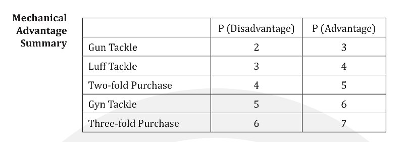 And no way am I a professor. I knew next to nothing before I started to research all this stuff for the tow boom project. I think of it this way: the suspended load is being held up by a pulley threaded with a number of lines. Each line takes an equal portion of the load. If you are lifting 100 lbs with a luff tackle in rove disadvantage, that configuration has 3 lines reeved to the moving pulley, and each line is taking on 33.3 lbs. So the line you are hauling on takes 33.3 lbs to move the load (MA=3). If you thread the lines so you are luff tackle rove advantage, that configuration has 4 lines reeved to the moving pulley. Each line bears 25 lbs now, and you only have to haul 25 lbs to move the 100 lb load (MA=4). Of course you have to pull 4 feet of line to get one foot of lift with a MA=4, so increasing MA means you need to pull increasing amounts of line for the same amount of lift. Now I have started collecting vintage pulleys, just because they are cool. Last edited by Arisaka on Thu Feb 13, 2020 3:23 pm, edited 2 times in total. |
| Thu Feb 13, 2020 2:03 pm |
|
|
Site Supporter  Location: Downtown Newcastle Joined: Sat Mar 5, 2016 Posts: 3447 Real Name: Traut |
Once again you've demystified something I've suspected a long time. Makes perfect sense the way you explain it, Sensei. Wax on, whacks off. Simple!
 thanks. thanks._________________ I always thought growing old would take a lot longer..... So, when does that "Old enough to know better" shit kick in??? I've learned that pleasing everyone is impossible, but pissing everyone off is a piece of cake. |
| Thu Feb 13, 2020 2:54 pm |
|
|
Site Supporter Location: Tacoma Joined: Sat May 4, 2013 Posts: 6214 |
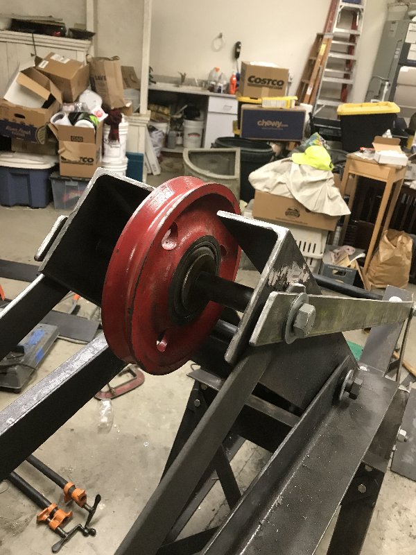
Most of the structure is done, so it’s time to mount the winch and pulleys. I started with the pulleys. The boom has three pulleys. The first one just redirects the angle of pull, while the other two are part of the lifting tackle. The first pulley is mounted at the tip of the main boom. The pulley is 8 inches OD and 2 inches ID. My Model T buddy turned me reducing spacers with a 3/4” center hole, so I could use a 3/4” grade 5 bolt for the pulley axle. Here is that first pulley.
 The other two pulleys are mounted in the boom extension. The one at the tip is a duplicate of the first pulley, with the same reducing spacer. The second pulley is smaller, at 4 1/2 inches OD and 5/8” ID. I used 3/4” and 5/8” grade 5 bolts for the two pulley axles. Here they are 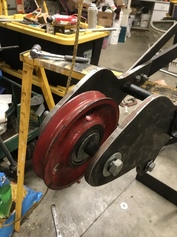 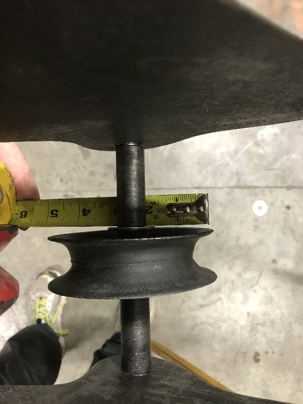 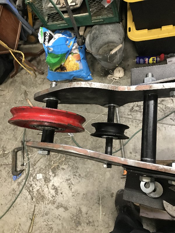 Here is a look at the pulley assembly 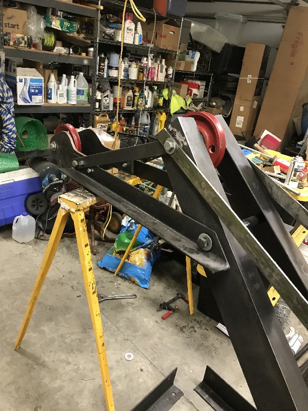 The winch was next. First job was to cut off the 4 legs welded to the winch 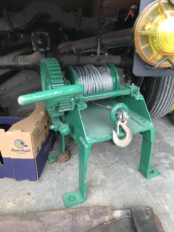 Then the winch was located in the boom so that when the boom is loaded in the truck bed, the winch handle would clear the 17” high sides of the truck bed. This is necessary because I will be extending the winch handle by 3 feet, so it can be operated from outside the truck. This is how it was done back in the day. 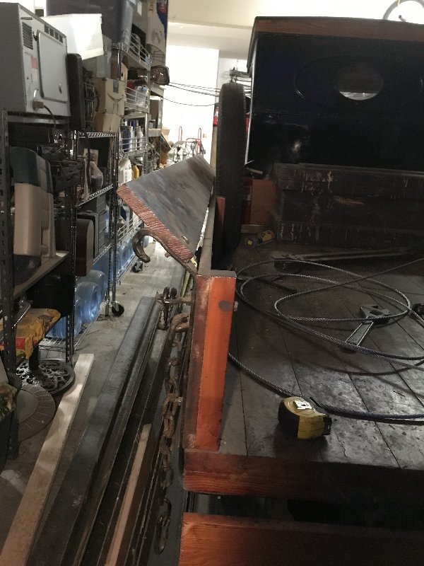 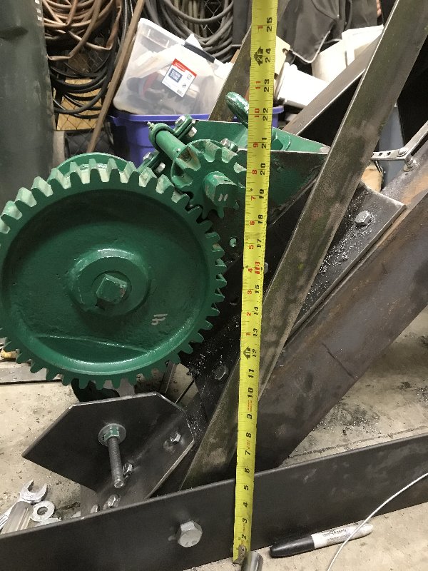 I fabricated some mounts for the winch from some angle iron. Here are a couple of pics 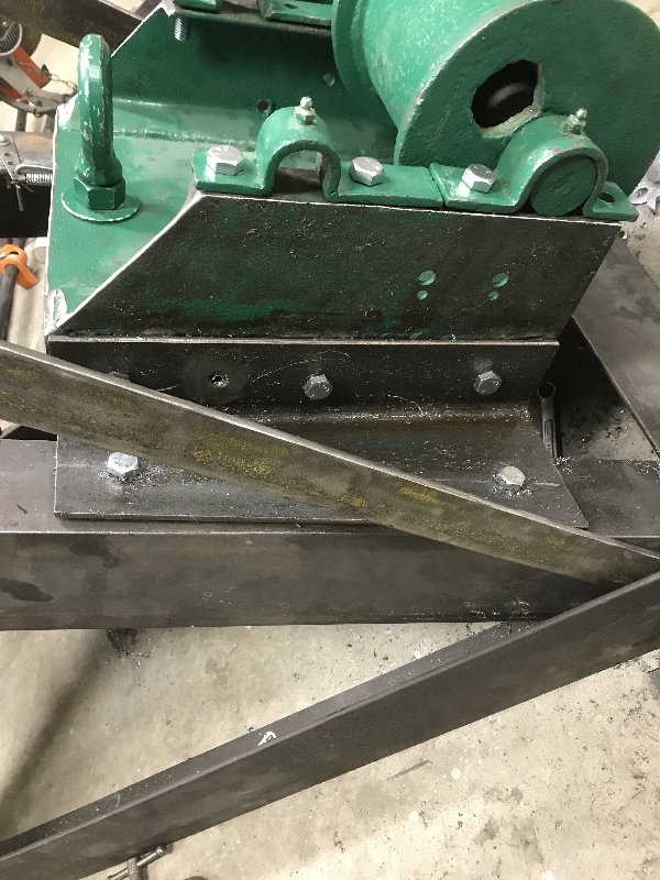 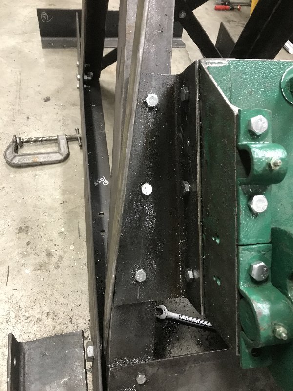 Half inch bolts are used to attach the winch to the boom 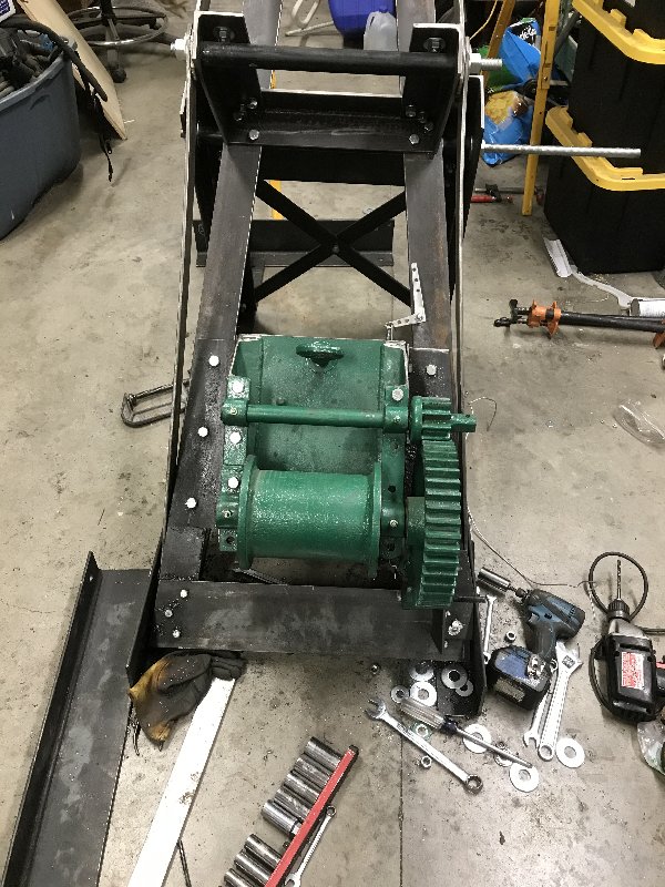 I needed to move the pawl location, as it’s original location interfered with the boom arm. The pawl is basically a brake. It’s an arm that projects into the spool gear teeth, preventing spool from unwinding. The pawl is rotated to disengage the spool gear teeth, so a load can be lowered. I had to fabricate a mounting bracket to hold the pawl. 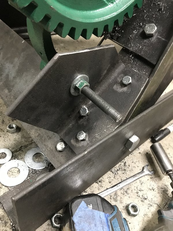 You can see the pawl in the background of the previous pic, but here are some more pics 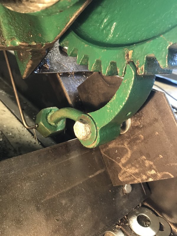 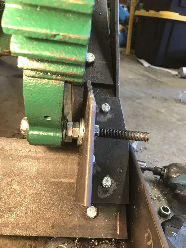 It is necessary to be able to release the pawl from outside the truck, so you can lower a load. To do that I needed some method to release the pawl from a distance of 3 feet away. Additionally, releasing the pawl requires that it be pulled in a rearward direction. However, I wanted to pull from the side of the truck, not the rear. There are many ways to redirect direction of pull. Pulleys and cables are commonly used. But I wanted a positive linkage that would push the pawl closed as well as pull it open. To do this I chose to make a simple bell crank. A bell crank is an L-shaped arm, with holes for linkages. When you pull on one leg of the bell crank, it exerts a pull 90 degrees to your pull. 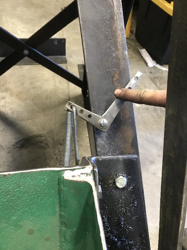 The other end of the linkage goes to the back of the pawl 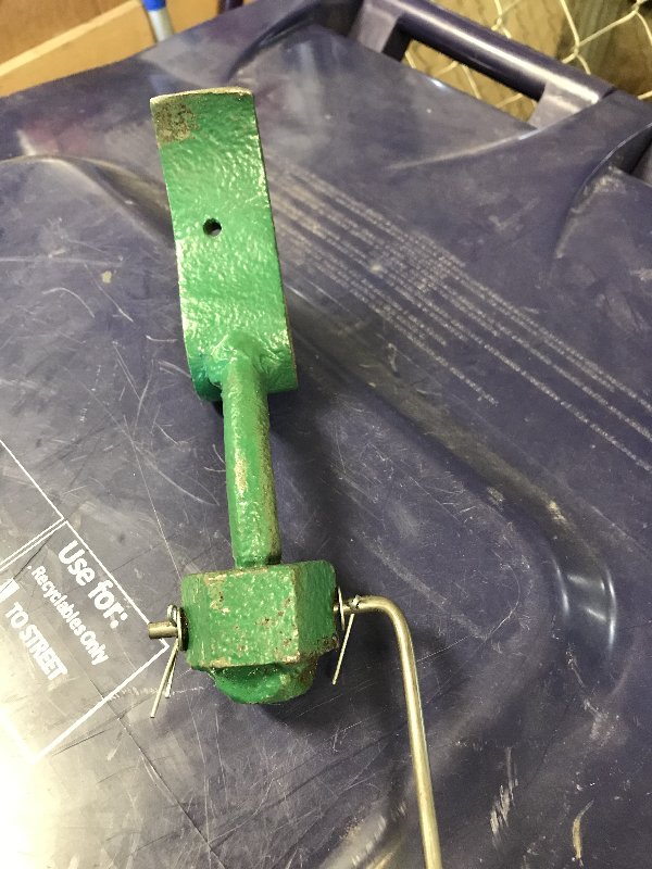 The pawl is gravity-activated to close, but I decided to add a spring to help draw it closed. 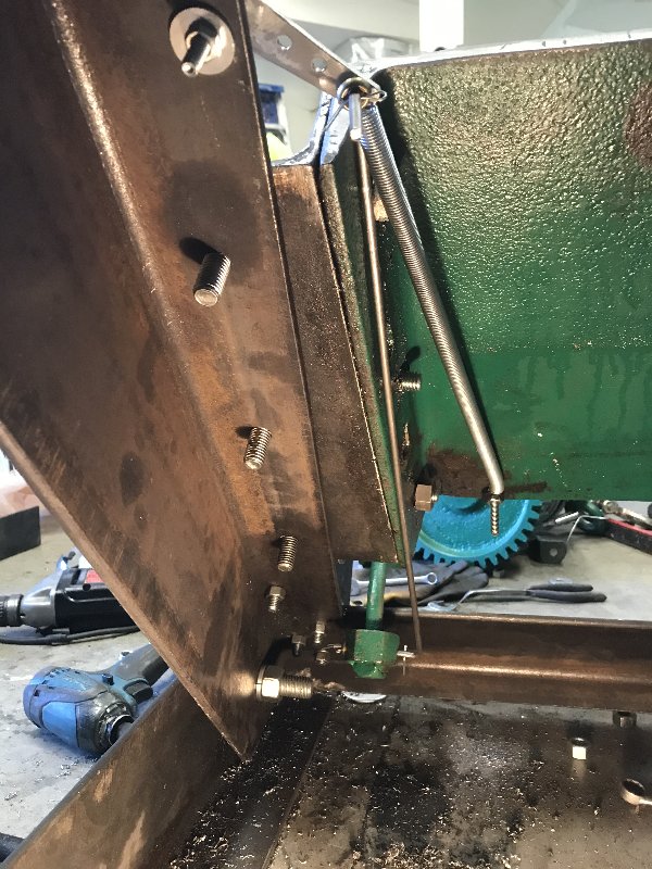 A couple of more pics 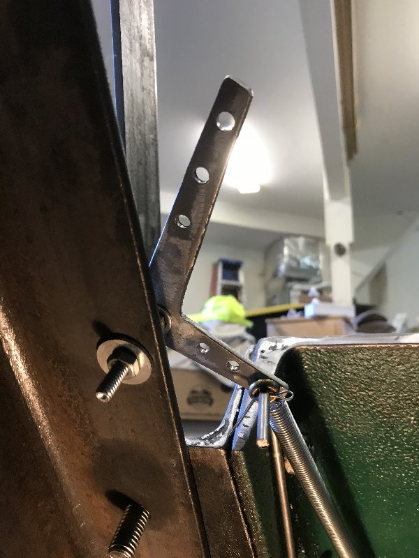 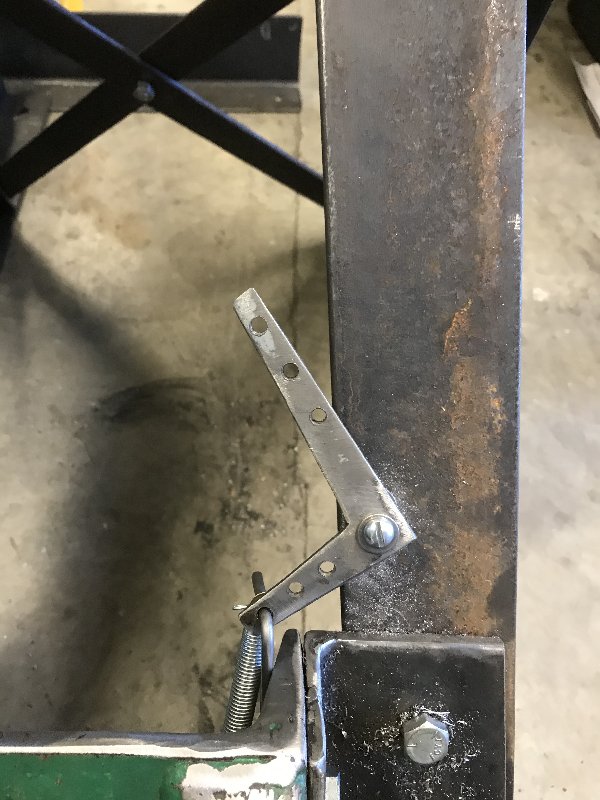 Next up is taking the whole thing apart and painting it. Then I have to reinforce the truck bed, mount the cradle frame, and drop in the boom. Then I can get to the extended winch handle, and finish the pawl linkage from the bell crank to the side of the truck |
| Wed Feb 19, 2020 6:32 pm |
|
|
Site Supporter Location: Snohomish Co Joined: Thu Sep 13, 2018 Posts: 1811 |
If you want to make a matching trailer there was a ford marked TT bed(i believe, i'm not too up on flatbeds) on craigslist for $100?ish. I didnt see it today so mabey it sold. I wanted it, but i have too many irons in the fire and didnt want to drive that far.
Also, I'm looking to get intimate with some pre '26 t roadster bodies using a tape measure, preferably in the north end. If you can direct me to anyone, i'd appreciate it. I picked up what appears to be mid 20's mutt/transitional body(Late sides, low cowl) and need to fab up a wood kit, it'll be v8-60 powered with a model a quickchange rear and model a axle up front, using a pair of t wishbones bent into hairpins. All pre 1950 stuff. |
| Sun Feb 23, 2020 12:03 am |
|
|
Site Supporter Location: Tacoma Joined: Sat May 4, 2013 Posts: 6214 |
Sent you a PM Shaggy
|
| Sun Feb 23, 2020 8:37 am |
|
 Location: Union Gap Joined: Sun Mar 27, 2016 Posts: 1722 Real Name: Randall Knapp |
Why not make a ratchet handle for the cable wench?
|
| Sun Feb 23, 2020 9:16 am |
|
|
Site Supporter Location: Tacoma Joined: Sat May 4, 2013 Posts: 6214 |
The tow boom is all disassembled and painted. While that is drying I started reinforcing the truck bed. The bed is supported by two lengthwise 4x6s, and decked with tongue and groove 2x6. Because of the weight of the boom, and the loads exerted by lifting and towing a disabled Model T, I wanted to reinforce the 4x6s. To do this, I cut two 6’ lengths of angle iron, and drilled them for 1/2” bolts, that would pass through the angle and the 4x6s.
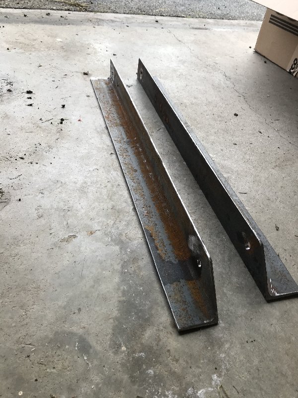 After painting them, I wrestled them into place alongside each 4x6. Then I cross drilled the 4x6s in 4 places to bolt up the angle iron. I had some salvaged 1/2 inch bolts from an old project, but the threads were in pretty rough shape 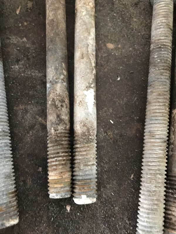 Each bolt got wire brushed, and I ran a die down each one 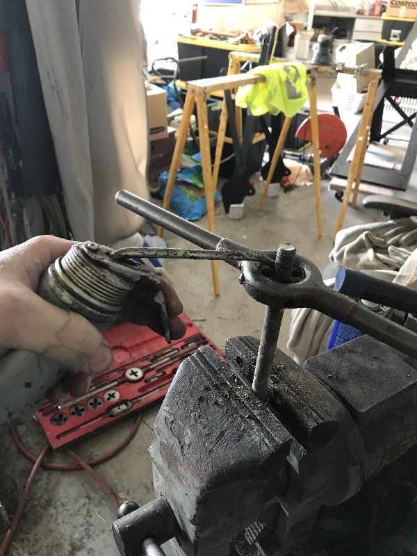 This gave me a chance to use a large tap and die set I inherited from my dad. It has taps and dies up to one inch. Dad was the last person to use this set. It’s been sitting in my garage for 15 years and I’ve never used it. 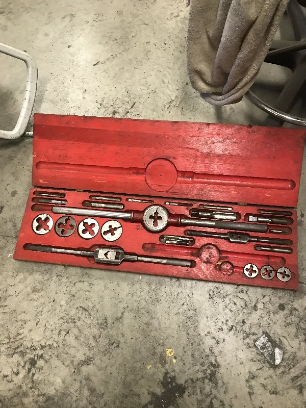 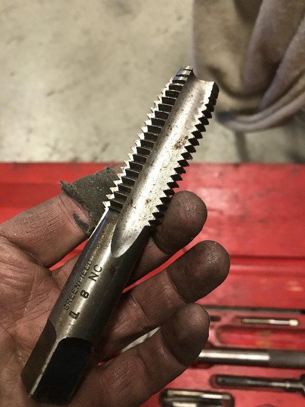 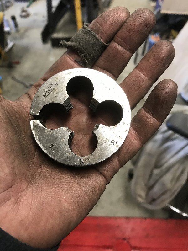 Here is one side all bolted up. 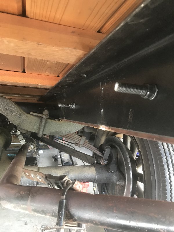 After I got both sides done, I took a look at how the bed was attached to the truck frame. That amounted to two 1/4 bolts on each side. That isn’t enough. I decided to beef that up with an additional two mounts per side. I made some mounts from 4” lengths of angle and bolted them to the truck frame. 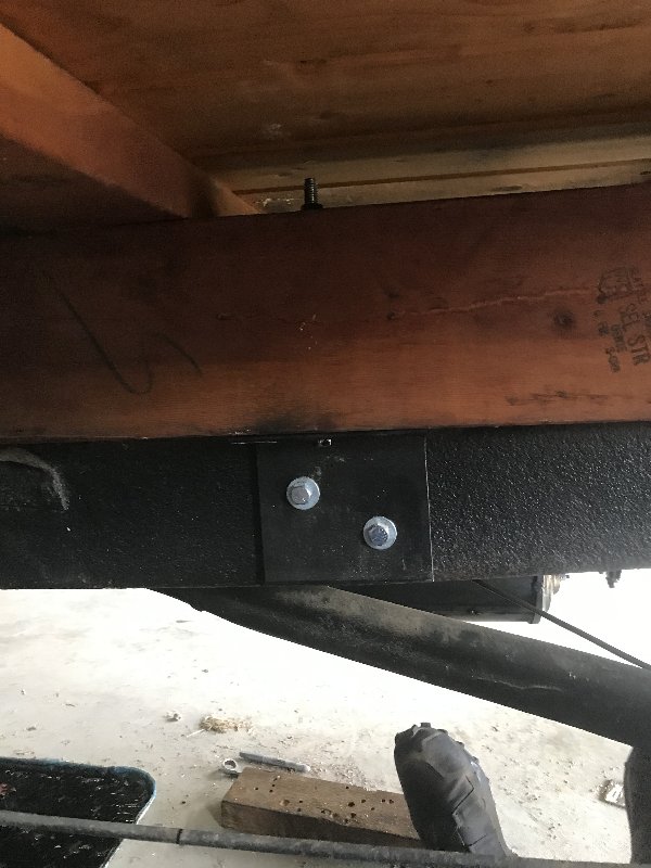 The 4x6s were drilled vertically, and 7-inch bolts were run through each mount and 4x6, and bolted 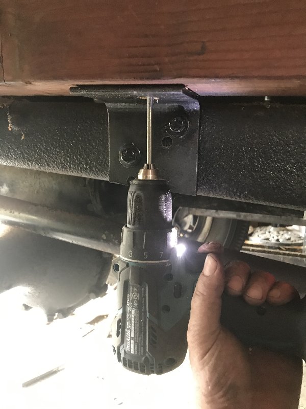 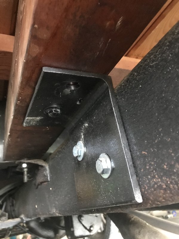 Now it was time to crawl out from under the truck and bolt down the boom frame in the bed. Each corner of the frame got 3/4” bolts down through the bed and through the angle iron reinforcing members beneath. Along the long arms of the frame I added 2 1/2” bolts per side 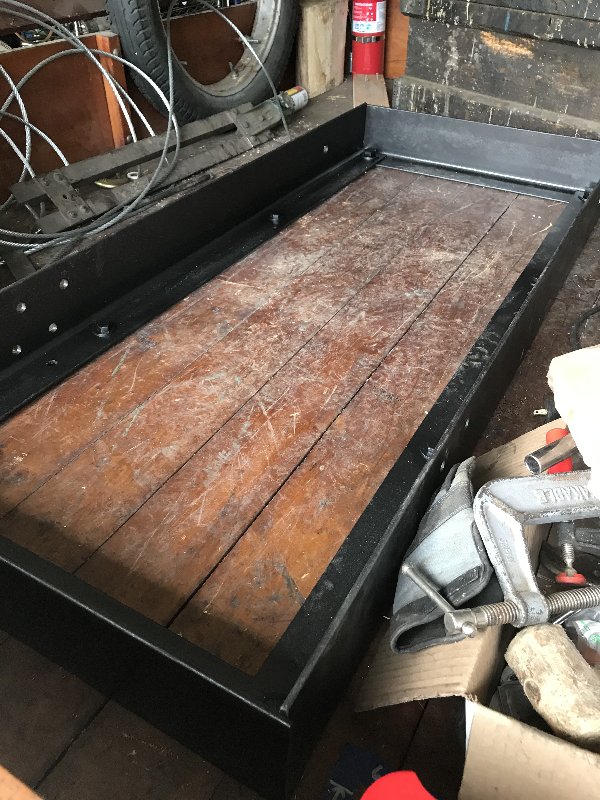 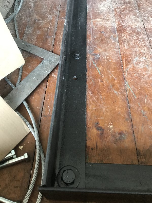 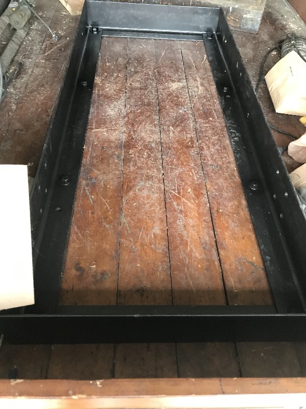 Tomorrow I will assemble the tow boom. Thursday, RocketScott is coming by with his boom truck to lift the tow boom into the back of my old truck. I will capture and post video of that! |
| Tue Feb 25, 2020 4:52 pm |
|
|
Site Supporter  Location: Kentucky Joined: Fri Jan 16, 2015 Posts: 11088 |
Gonna be sweet!
_________________ You may be right, I may be crazy, but it just may be a lunatic you're looking for |
| Tue Feb 25, 2020 6:36 pm |
|
|
Site Supporter  Location: Everson, WA Joined: Sun Jan 6, 2013 Posts: 28178 Real Name: Ace Winky |
You had me at "wood".
   _________________ Why does the Penguin in Batman sound like a duck? Because the eagle sounds like a hawk. |
| Tue Feb 25, 2020 6:45 pm |
|
|
Site Supporter Location: Downtown Newcastle Joined: Sat Mar 5, 2016 Posts: 3447 Real Name: Traut |
Is there a dual axle and overload springs available for those trucks?
Seems like the weight is starting to add up, which also makes me wonder about the brakes. You're probably on top of that. How much weight do you think you've added?_________________ I always thought growing old would take a lot longer..... So, when does that "Old enough to know better" shit kick in??? I've learned that pleasing everyone is impossible, but pissing everyone off is a piece of cake. |
| Tue Feb 25, 2020 7:30 pm |
|
|
Site Supporter Location: Tacoma Joined: Sat May 4, 2013 Posts: 6214 |
Traut wrote: Is there a dual axle and overload springs available for those trucks? Seems like the weight is starting to add up, which also makes me wonder about the brakes. You're probably on top of that. How much weight do you think you've added?I expect it will be around 400-500 lbs when all is said and done, But it’s a 1 ton truck, so that shouldn’t be an issue. And you are right about needing better brakes when the weight goes up. Last year I put hydraulic disc brakes on the back axle. They work very well and lock up both tires on blacktop. The limiting factor is a small contact patch with 4.5” tires. On the upside, I really can’t get this old girl much above than 25 mph, and she is much happier at 20. |
| Tue Feb 25, 2020 8:51 pm |
|
|
Site Supporter Location: Kentucky Joined: Fri Jan 16, 2015 Posts: 11088 |
We’ll go slow lowering it on. Just to be safe
With all the pictures of the same/similar setup I can’t see how it would be a problem Sent from my iPhone using Tapatalk _________________ You may be right, I may be crazy, but it just may be a lunatic you're looking for |
| Tue Feb 25, 2020 9:52 pm |
|
|
Site Supporter Location: Downtown Newcastle Joined: Sat Mar 5, 2016 Posts: 3447 Real Name: Traut |
I didn't realize it was a 1 ton rated vehicle. Should be fine. I've just seen a lot of projects go sideways due to adding a little accessory here and there until a rig's capacity gets compromised or at least the handling characteristics changed enough to surprise the operator. In this case my comment was made in semi jest. Arisaka is running a tight ship. As I watch the project progress I'm always impressed with the creativity and workmanship, but one of the main things that is always in the back of my mind, and I'm sure is ever present while the work is going on, is what a remarkable tribute the project is to Arisaka's Dad. You can always tell the subtle differences in endeavors that are labors of love. Pop would be mighty proud.
_________________ I always thought growing old would take a lot longer..... So, when does that "Old enough to know better" shit kick in??? I've learned that pleasing everyone is impossible, but pissing everyone off is a piece of cake. |
| Tue Feb 25, 2020 11:34 pm |
|
|
Site Supporter Location: Tacoma Joined: Sat May 4, 2013 Posts: 6214 |
Traut wrote: I didn't realize it was a 1 ton rated vehicle. Should be fine. I've just seen a lot of projects go sideways due to adding a little accessory here and there until a rig's capacity gets compromised or at least the handling characteristics changed enough to surprise the operator. In this case my comment was made in semi jest. Arisaka is running a tight ship. As I watch the project progress I'm always impressed with the creativity and workmanship, but one of the main things that is always in the back of my mind, and I'm sure is ever present while the work is going on, is what a remarkable tribute the project is to Arisaka's Dad. You can always tell the subtle differences in endeavors that are labors of love. Pop would be mighty proud. Thank you for the kind words, Traut. Perhaps we can take the old truck out for a spin sometime! |
| Wed Feb 26, 2020 8:26 am |
|
|
Site Supporter Location: Snohomish Co Joined: Thu Sep 13, 2018 Posts: 1811 |
Traut wrote: Is there a dual axle and overload springs available for those trucks? Seems like the weight is starting to add up, which also makes me wonder about the brakes. You're probably on top of that. How much weight do you think you've added?They made 15 million model t's over 19 years with only minor changes, they made anything you can think of aftermarket. Some of it great, some of not so, but you could do anything you wanted with them. As he mentioned though a TT truck is the heavy duty twin, stouter frame and springs amoung other stuff. |
| Wed Feb 26, 2020 9:44 pm |
|
|
|
Page 18 of 31 |
[ 454 posts ] | Go to page Previous 1 ... 15, 16, 17, 18, 19, 20, 21 ... 31 Next |
|
All times are UTC - 8 hours |
Who is online |
Users browsing this forum: No registered users and 44 guests |
| You cannot post new topics in this forum You cannot reply to topics in this forum You cannot edit your posts in this forum You cannot delete your posts in this forum You cannot post attachments in this forum |